General Technical Help
General Technical Help olcadminThis section contains pages and links to technical information that may be useful when undertaking restoration and preservation projects. Some of the content was created by The Old Lawnmower Club and some of it is in the form of links to other sites.
General Hand Mower Advice
General Hand Mower Advice olcadminHand mower components such as T handles and rear rollers for sidewheel mowers and hand grips and front rollers for roller mowers were often made of wood. These inevitably disappear over time through damage, rot or wood worm and replacing them with original parts can be almost impossible. We generally recommend asking a local woodturner or hobbyist to make up new parts using what remains of the old ones as a pattern. There is usually someone in most towns who knows how to use a lathe and they are often only too happy to help with this sort of thing. To find them, ask in the local ironmongers or wood yard as they are likely to be known there. Yellow pages is also a good place to look. When you have found someone, ask them to use ash, beech or elm for the greatest authenticity. As a guide, hand-grips on Greens roller mowers were normally of beech, but Ransomes used ash up to the late 1930s, when they too started using beech. T-handles on side-wheel mowers made in the UK were usually ash up to the 1930s, when beech came in. American side-wheel mowers often have maple handles, though Pennsylvania handles (UK and US) are usually ash.
Grass Boxes
Grass boxes inevitably go missing or simply disappear before your eyes due to rust and rot. In fact, many side-wheel mowers may never have had a box in the first place as it was normally an "optional extra" for these machines. As might be expected, finding a replacement box is virtually impossible. It is occasionally possible to find spare boxes at car boot sales, junk shops and especially at mower repairers but the chances of matching the right box for a particular mower are slim. Boxes for mowers such as the Ransomes Ajax, Webb models from the 1950s and a few other machines can still be found in this way with a bit of persistence.
For all other mowers there is no simple answer as making one from scratch is often beyond the capabilities of most enthusiasts and the cost of asking a professional engineer or carpenter to do the work can be prohibitive. However, anyone with the right skills should be able to copy an existing box using the original as a pattern or basic dimensions supplied by another enthusiast. Early boxes can be relatively easy to fabricate because they had simple wooden sides with the box formed by a thin sheet of steel. The box mounted on the mower by simple brackets that can often be easily copied (if those from the original are no longer available) and made from steel or aluminium rather than cast iron. Once painted nobody would be able to tell the difference.
Block Chain
The original block chain used on many hand mowers before 1914 cannot be supplied and we know of no current source. The only way to replace a missing or broken chain is to use a redundant length from an old "donor" machine.
Cast Iron Components
Most early mowers were made using cast iron components. While original replacements for these are no longer available copies can be made using modern castings. Although decreasing in number there are still many small iron foundries around the country that can make castings in small numbers to order using originals as a pattern. Members of The Old Lawnmower Club have, over the years, managed to obtain items such as chain sprockets, gears, gear covers, handles and grass box handles/brackets made in this way. It is sometimes possible, and usually cheaper, to make the casting from aluminium rather than iron and there are more foundries that can offer this service. An alternative method is to machine a copy using steel or aluminium.
General Motor Mower Advice
General Motor Mower Advice olcadminType Of Petrol
One of the commonest queries to the club is about the correct type of petrol to use with a vintage lawn mower. Although many old motor mowers with four stroke engines were made during the period when leaded petrol was standard the prevailing view is that these machines will run perfectly well on ordinary modern unleaded fuels. Lead based additives were used in petrol to help lubricate valves and prevent preignition on four stroke engines. However, old mower engines do not generally run fast enough, hot enough or at sufficient compression ratios for the presence of an additive to be a major factor. Two stroke engines do not require leaded fuel or additives.
Smaller and faster running engines made after about 1970 may benefit from use of an additive. Local mower repair shops will be able to advise customers on mowers with this type of engine which falls outside the scope of the Old Lawnmower Club.
Spark Plugs
Many older motor mowers require 18mm spark plugs that are no longer available. Some specialist vintage engine part suppliers may be able to assist.
A useful source that cross-references some old spark plug number with the modern equivalent can be found here.
Villiers Magneto Rebuild
Villiers Magneto Rebuild olcadminThese simplified instructions are intended as a guide for anyone attempting to strip down and repair a similar ignition system. The Atco mower which was being serviced was the Deluxe model from the 1930s although the same engine was used on many of the company's earlier models from the 1920s as well as later machines up to 1939 and after.
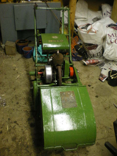
It is advisable to have a set of Whitworth combination spanners available. These are a huge benefit compared with using a “close match” metric or standard Imperial spanner. The use of adjustable spanners is particularly unsuitable when having to apply the rather large torques for removing or re-fitting the flywheel.
1: Ignition System Access
1: Ignition System Access olcadmin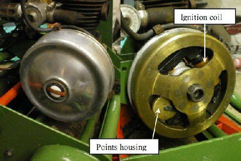
Gain access to the ignition system by prising off the aluminium casing from the side of the engine. This will reveal a heavy brass flywheel with access holes for checking points.
The contact breaker points are housed beneath the brass cap (see image) whose retaining arm must be swung sideways to open the cap. With a little careful manoeuvring, the cap can be removed through the access holes in the flywheel and the points gap can be checked and adjusted. The gap should be checked (probably 0.015”) and adjusted using the threaded adjuster and locknut as required.
2: Removing The Flywheel
2: Removing The Flywheel olcadmin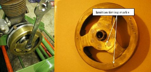
To perform any maintenance on the ignition system other than cleaning or adjusting the points, it is necessary to remove the flywheel. This is best achieved by jamming the flywheel (to prevent its rotation) with a wooden wedge between its outer circumference and a mower cross bar.
Then, using an appropriate ring spanner, give a sharp strike to the ring spanner with a hammer in an anticlockwise direction to shock the nut undone (see image). A 1/2in Whitworth ring spanner can be used however, if one can be found, Villiers also produced a special spanner (called a Hammertite spanner) for this specific task. This has a ring spanner at one and a place to hit with a hammer at the other.
If successful, the nut will undo by about one or two full turns before apparently locking-up again. You need to shock this anticlockwise again which will then prise the conical flywheel mount from the mating taper on the crankshaft; the nut is captive but rotates within the flywheel.
The magneto flywheel contains a pair of permanent magnets and the original Villiers maintenance advice was to place a piece of iron (e.g. a spanner) to bridge across the poles thus preventing loss of magnetic flux.
3: Removing The Armature Back Plate
3: Removing The Armature Back Plate olcadmin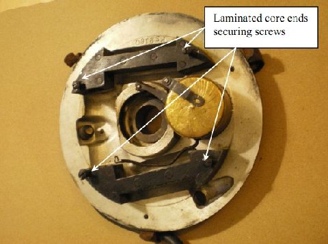
To inspect or service the ignition system, it is easiest to remove the whole magneto assembly from the engine. Disconnect the H-T lead from the spark plug. Loosen the set screw which is behind the armature back plate and which clamps the back plate on to the engine’s crank housing.
The back plate is also clamped to the crank housing with a support bracket. On some Villiers ignition system, there is an alternative clamping arrangement allowing some rotation of the back plate so as to “tune” the ignition timing.
With a bit of back-and-forth rotation of the back plate around the axis of the crankshaft, the entire armature back plate should come away from the engine (see image) and can be overhauled more easily on a well-lit and clean workbench (to avoid losing small but crucial parts).
4: Checking or Replacing The Ignition Coil
4: Checking or Replacing The Ignition Coil olcadminIf the engine is suffering from a weak (or no) spark, then the problem may be within the magneto coil. This can be checked using a voltmeter (to measure resistance) but it is required to remove the wire connection between the coil and the points.
The primary winding should have a resistance of just a few Ohms (measured between ground - either end of the iron core - and the socket in to which the points wire was screwed.) The secondary winding resistance should be 3-5k Ohms and this can be measured between the side terminal connection to the H-T lead and ground.
The most likely scenario with an old magneto coil is that it has some internal corrosion and the secondary winding (which is wound from extremely fine copper wire) has broken.
The coil can be removed from the “shoe” shaped laminated metal core ends by removing the nuts on the rear side of the back plate. You may need to use a screwdriver to counteract the torque on the corresponding screws which hold these core ends on to the back plate (see image). The core ends will then lift from the back plate and the coil can be pulled free from these shoes.
Replacement coils can be sourced via the internet but ensure that you specify the correct length and end diameters as there are various models available. Replacements are not cheap (perhaps £50) and beware of untested items for sale on auction sites!
With the flywheel removed, you now have excellent access to the contact breaker points and can provide a proper inspection.
5: Contact Breaker Points Maintenance
5: Contact Breaker Points Maintenance olcadmin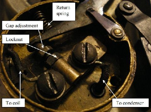
Disassemble the points by removing the contact breaker arm. This is held in position by a clip and spring. Note that the spring may easily be dropped on the floor – hence the need for a clean, well-lit work surface.
Loosen and remove the two screws which hold down the brass strip and which also clamp the low tension wire and the connection to the condenser. This brass strip is isolated from ground by insulating posts which should be inspected for cracks or other degradation. Note the order of construction of these components so that it can be rebuilt easily.
With the upper components removed, the base of the points housing can be unscrewed from the back plate and the capacitance of the condenser can be measured. The condenser rarely fails.
Reassembly is generally the reverse of the disassembly instructions above, but pay particular attention to the cleanliness of the contact breaker points. Even a thin film of oil from dirty feeler gauges can foul the points surfaces sufficiently to prevent a good spark.
6: Inspecting The H-T cable
6: Inspecting The H-T cable olcadmin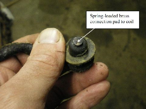
Inspect the H-T cable for continuity between the spring-loaded coil end and the spark plug connection end.
Check also for cracks in the cable insulation. Replacement cables can be sought from the internet, but repairs can also be made to cracked or otherwise damaged H-T leads using appropriately-sized adhesive heatshrink.
7: Re-fitting The Flywheel & Final Set-up
7: Re-fitting The Flywheel & Final Set-up olcadmin
Hold the contact breaker arm open while refitting the flywheel on to its tapered shaft. There are timing marks on the flywheel which should be aligned with the notch on the crankshaft end. This will ensure correct spark timing.
The flywheel nut will need to be tightened sufficiently to prevent any movement on the tapered shaft. If it is slightly loose, the flywheel may slip following a misfire, the timing will be compromised and the engine will run either roughly or not at all. Therefore, tighten the flywheel using the ring spanner and hammer arrangement previous described for removal, but this time for tightening (clockwise).
Finally, re-set the contact breaker points gap.
Check for a spark by unscrewing the spark plug, attaching the H-T lead and resting the threads of the plug against the surface of the cylinder’s cooling fins.
Freeing A Seized Atco Cone Clutch
Freeing A Seized Atco Cone Clutch olcadminThis simple cone clutch was used on a variety of Atco products including the “Lightweight” lawnmower and also, as in this case, the Atco Scythe. During restoration work on items which have been left outside or inactive for many years, parts which should me moving – aren’t!
The following instructions are taken from a simple overhaul of a seized clutch without the aid of any specialist tools. We hope they will be of some help to others. These instructions have been written without access to the original manual for this equipment.
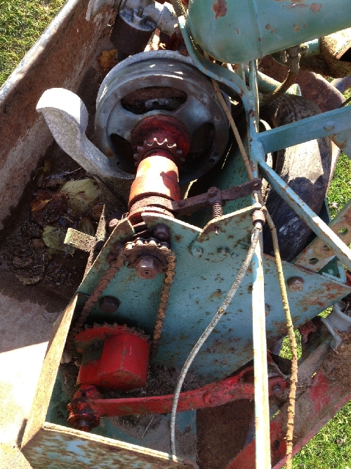
Figure 1: The clutch and chain drive to the reciprocating blade of this Atco Scythe. Exposure to the elements had taken its toll on most aspects of this machine.
1: Removing Clutch Assembly
1: Removing Clutch Assembly olcadminThe first step is to remove the clutch assembly from the drive train. This is required anyway to gain access to the flywheel retaining nut and thereby access to the ignition system. The chain shown in Figure 1 has a removable link making its disassembly simple. The use of penetrating oil then allows the sprocket retaining nut to be removed, followed by the sprocket itself from the splined shaft.
More penetrating oil enables the three nuts and bolts which hold the clutch ball bearing cassette to be removed, and after releasing any tension on the clutch cable, disassemble the clutch release forks assembly. A useful tip at this point is to store the disassembled nuts, washers and spring in the order ready for reassembly….or to photograph the details of this assembly order.
Depending on how much clearance you have, you may or may not be able to remove the clutch assembly from the machine. In the case of this Atco Scythe, the engine needed to be shifted slightly to provide sufficient clearance to remove the clutch. The clutch is attached to the flywheel via the tabbed shaft and the associated slots in the outer clutch body housing as shown in Figure 2.
2: View of Flywheel Assembly
2: View of Flywheel Assembly olcadminIt is tempting to try to remove the slotted screw head which is presented within the clutch housing at this time, however, it’s not necessary to remove this for a general clutch overhaul and, at time of writing, the author still doesn’t know if this is a left- or right-handed thread; the direction of rotation would suggest a left-hand thread to be most appropriate. But in summary, the screw’s removal is not fundamental to separation of the friction surfaces.
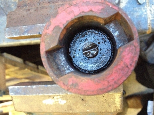
Figure 2: View of flywheel end of clutch assembly.
3: Clutch Assembly Removed From Engine
3: Clutch Assembly Removed From Engine olcadmin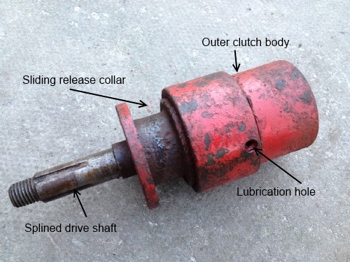
Figure 3: Clutch assembly once removed from engine. At this point, the friction surfaces are seized and stuck together.
In this case, it was possible to begin rotating the outer clutch body relative to the drive shaft, but with an insufficient clearance to allow the clutch to mesh and disengage to any useful degree.
The main seizure problem was that the sliding release collar simply wasn’t (sliding) and was stuck fast to the drive shaft. The lubrication hole is of some use here because it allows penetrating oil to lubricate the engine end of the drive shaft. Note that the lubrication hole doesn’t duct lubricant on to the friction surfaces, but more lubricates components within the outer clutch body. Penetrating oil should also be introduced from the sprocket end in an attempt to free the release collar.
4: Removing Collar From Drive Shaft
4: Removing Collar From Drive Shaft olcadmin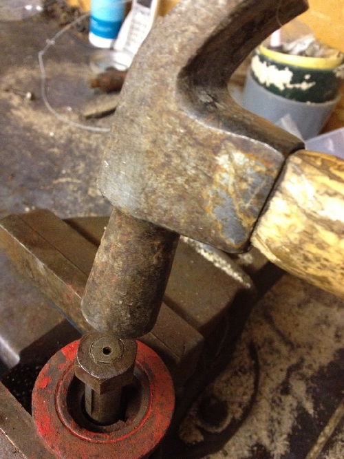
Figure 4: Holding the release collar whilst tapping the drive shaft free.
The next operation is somewhat controversial: you need to begin working the drive shaft back and forth, applying more penetrating oil as necessary, so that little-by-little, the drive shaft begins to move relative to the release collar. I first tried a 3-legged wheel puller for this operation but found that I had applied so much force without any success that I feared breaking off pieces of the release collar. Figure 4 shows the sprocket retaining nut having been screwed on to the end of the drive shaft to be flush with the threaded end of the shaft. This can then be tapped “sharply” with a hammer to help shock the shaft free of the collar whilst supporting the release collar on the jaws of a vice. It has to be understood here, that there is a significant risk of deforming the threads of the shaft, so some judgment needs to be made as to how hard to strike the shaft & nut. Tapping the shaft and clutch housing in opposing directions with the aid of penetrating oil in this case gradually freed the release collar from the shaft and allowed disassembly of the mating clutch cone surfaces as shown in Figure 5.
5: Release Collar and Cone Separated
5: Release Collar and Cone Separated olcadmin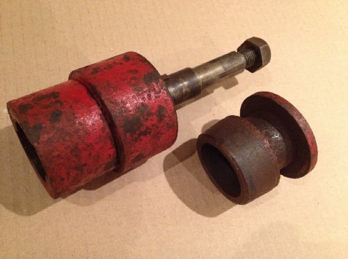
Figure 5: Release collar and its cone shown separated from main clutch parts.
The main clutch components are now separated and can be cleaned and reassembled, noting that the retaining screw shown in Figure 2 needn’t be disturbed.
Cleaning of the keyed drive shaft as shown in Figure 6 (being careful not to lose the Woodruff key) can now take place. Cleaning of the hole through the release collar clutch portion and its keyway should allow the release collar to slide easily along the drive shaft. Penetrating oil on a rag is sufficient to clean such surfaces. I didn’t bother cleaning anything but loose rust from the mating cone surfaces and assumed that the engagement of the cone surfaces during normal drive operation would adequately bed-in the parts.
6: Splined Shaft
6: Splined Shaft olcadmin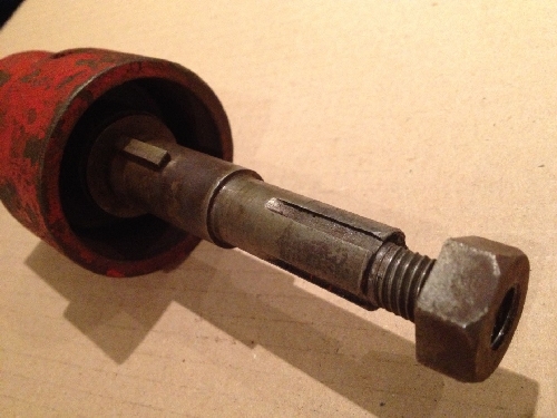
Figure 6: Splined drive shaft showing the Woodruff key which transmits the driving torque from the driven clutch half to the drive shaft.
7: Reassembly
7: Reassembly olcadmin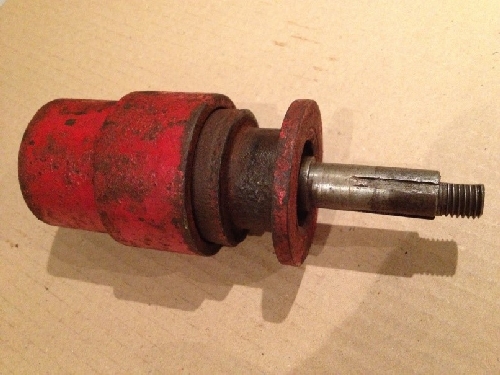
Figure 7: Reassembled clutch components.
Reassembling all the components in the same order as they were removed completes the task. I gave the clutch spring a slight stretch before re-fitting it as I assumed that the passage of time and the elements would have weakened this somewhat. I also washed through the ball race with petrol and re-greased it prior to reassembly in the end frame of the Atco Scythe.
Finally, you need to adjust the clutch release forks’ position and cable tension so that the clutch properly disengages (one doesn’t want the blade of an Atco Scythe to twitch when it should be stationary) and that the forks aren’t in contact with the release collar when the clutch is engaged.
The video shows the Atco Scythe up-and-running after restoration.
Villiers Two Stroke Engine Timing
Villiers Two Stroke Engine Timing olcadminThere's a useful explanation of how to time a Villiers two stroke engine here.