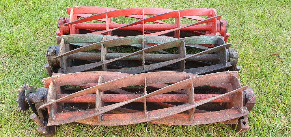
A brace of Ransomes Marquis - Restoration
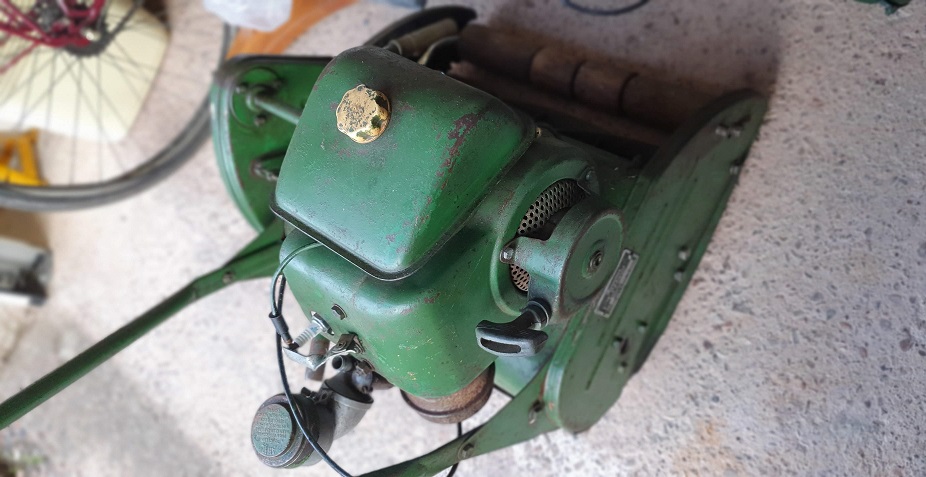
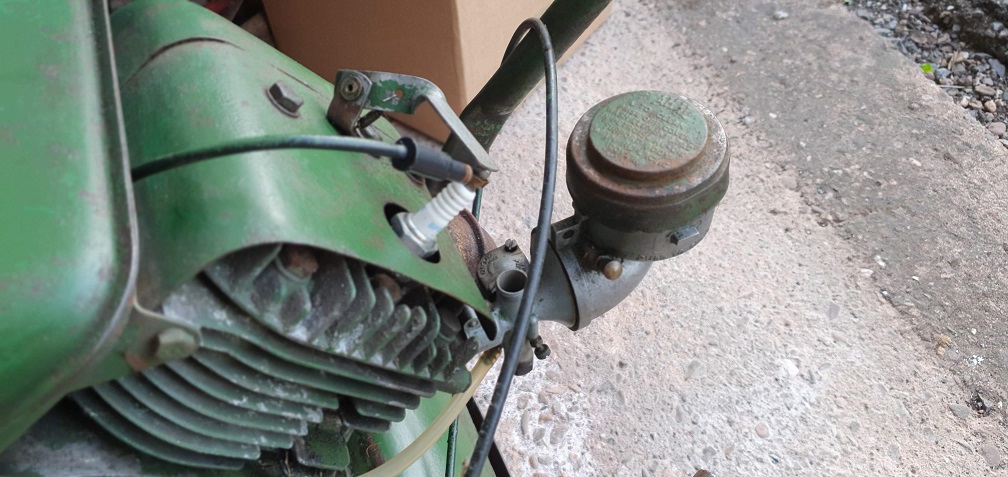
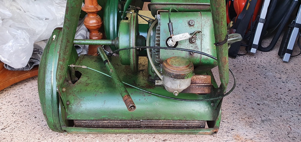
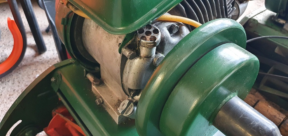
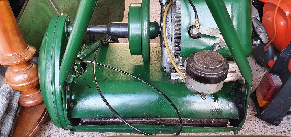
The finish line was in sight for my Atco / Suffolk Super Colt and I wanted to get something lined up for my next project. I spotted a Ransomes Marquis 18" non runner due to no spark (here we go again!), and when I went to look at it, the chap also had a running Marquis which was a slightly newer model, but had a fuel leak at the carb. Needless to say I ended up getting them both in the back of the car, with assistance!, and brought them home.
I'm not going to go to the lengths I went to with the Atco - as good a learning experience as that was, I now want to keep the mowers cosmetically as they are, bar a couple of little touch ups here and there, but overhaul them mechanically to get them both running well. Hopefully I can use one of them as my regular mower as the 18" cut will hopefully make things easier around the garden, and I do like the look of these mowers.
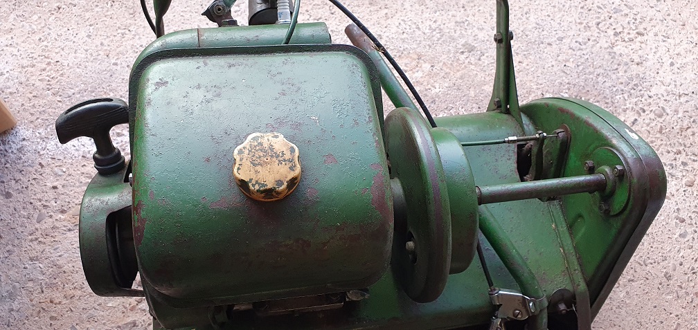
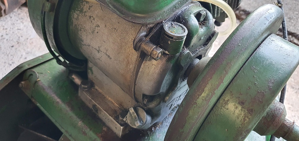
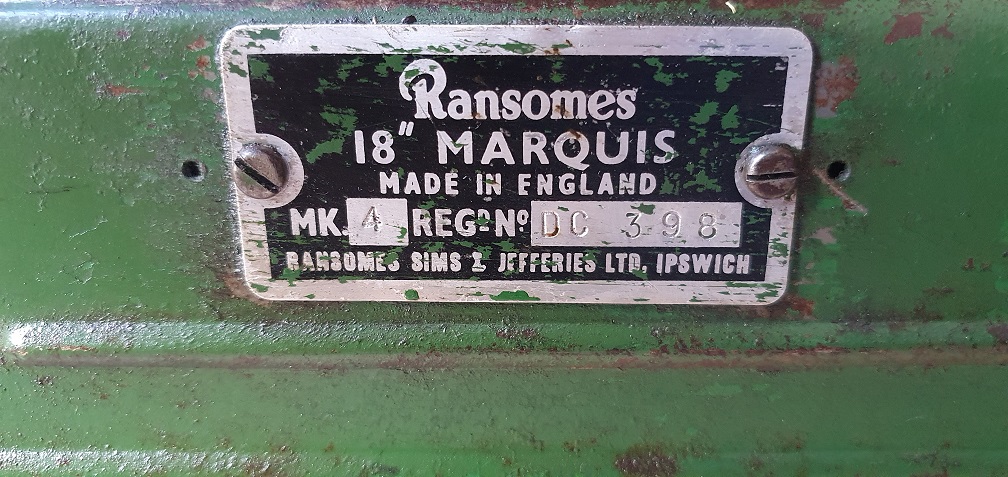
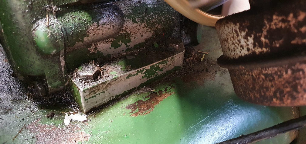
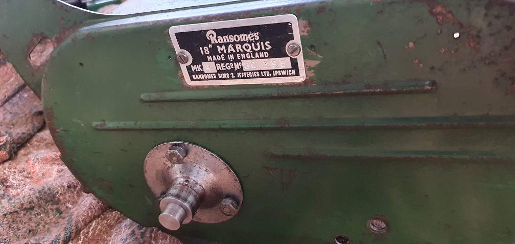
I would like to get an idea of manufacture date for both, and one should be easier as it has the plate on the side which says Mk4, but they both have the same BSA marked F12 Sloper engine
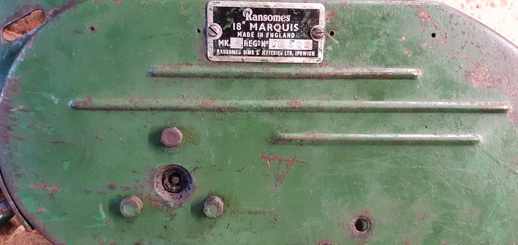
Mower 1 - Ransomes Marquis 18" Mk4 - Reg No. DC 398
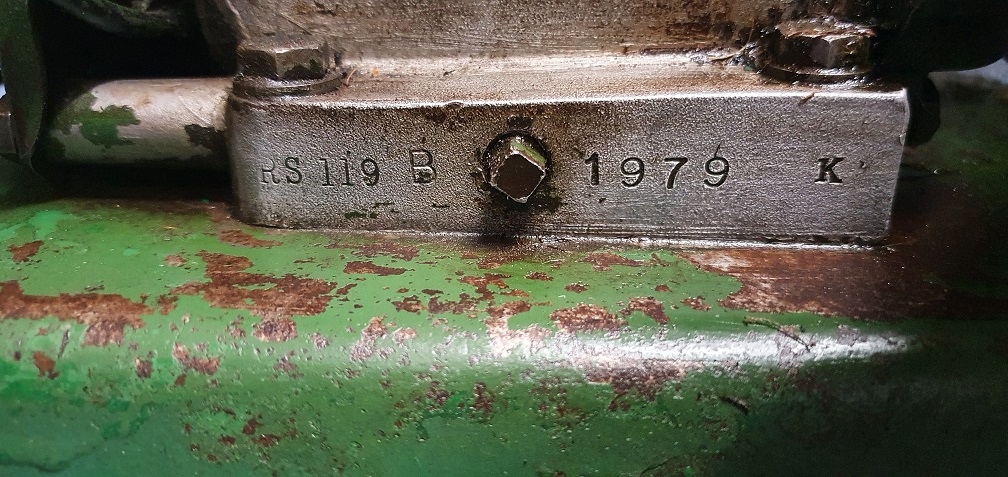
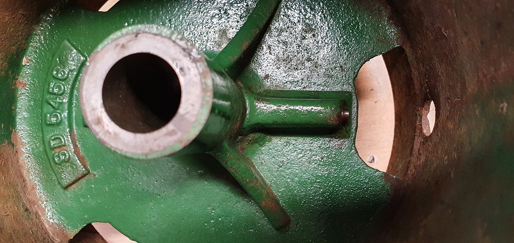
No numbers on the exhaust side of the block like the other mower, however the sump drain plug side has the following - RS 119 B 1979 K
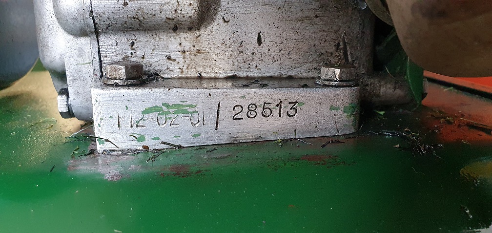
Mower 2 - Ransomes Marquis 18" Mk??- No ID Plate
Forums

Although pretty tight, I
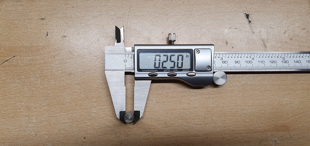
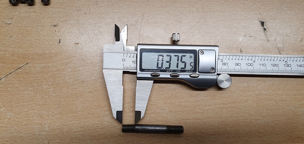
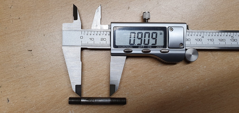
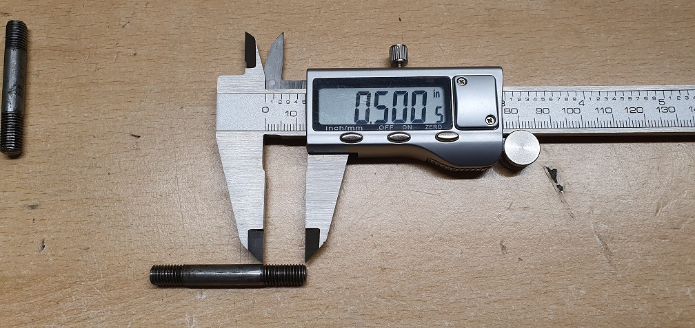
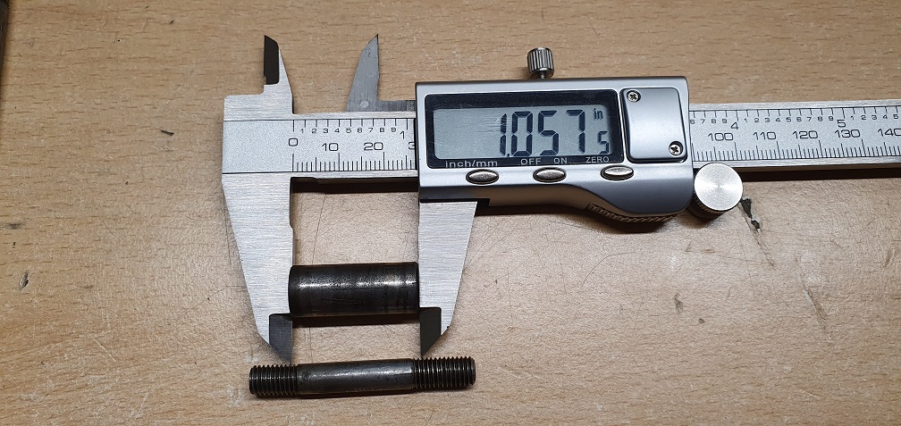
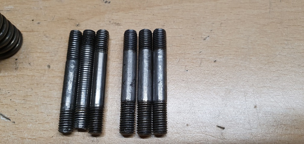
Although pretty tight, I managed to carefully remove the 3 studs from the mk4a Intermediate pinion with no damage, which appear to all match and be correct, so I could take some measurements.
No luck finding 'off the shelf' replacement UNF studs of the correct dimensions so far, so may have to go with a full thread length of stud, and cut it into the 3 required lengths. I was hoping these would have been used in another application somewhere, such as automotive, making them easier to source. The marquis parts list on this site doesn't show them with a part number, so they must come as part of the complete Intermediate pinion. The size format, based on my measurements, are: 1/4" UNF Stud with Fixed end thread length = 1.5 x diameter, smooth section = just shorter than the 1" long spacer, Nut end thread length = 2 x diameter
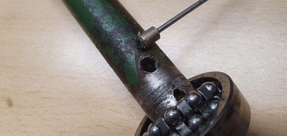
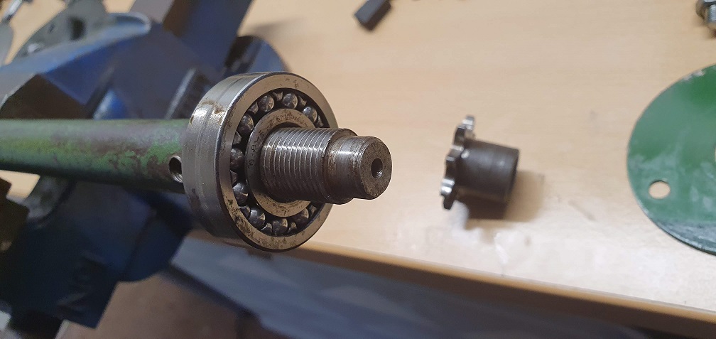
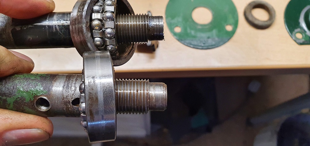
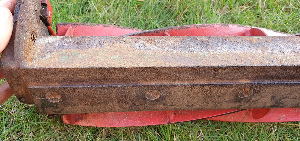
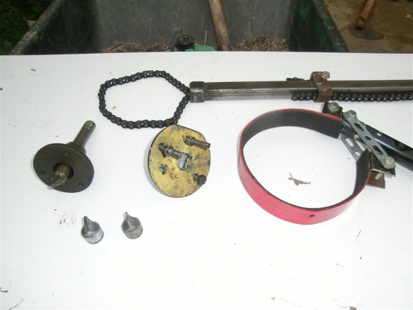
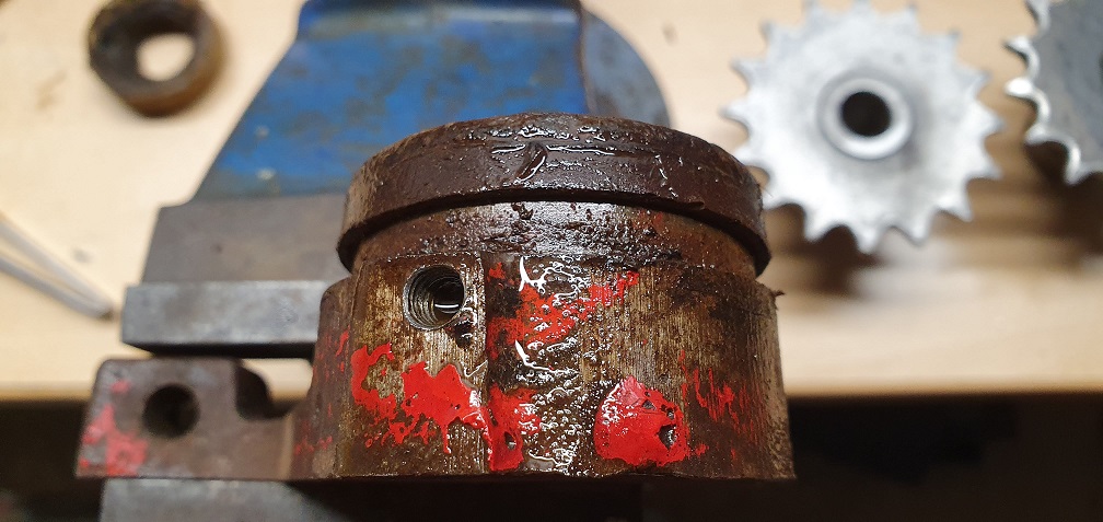
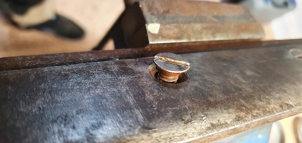
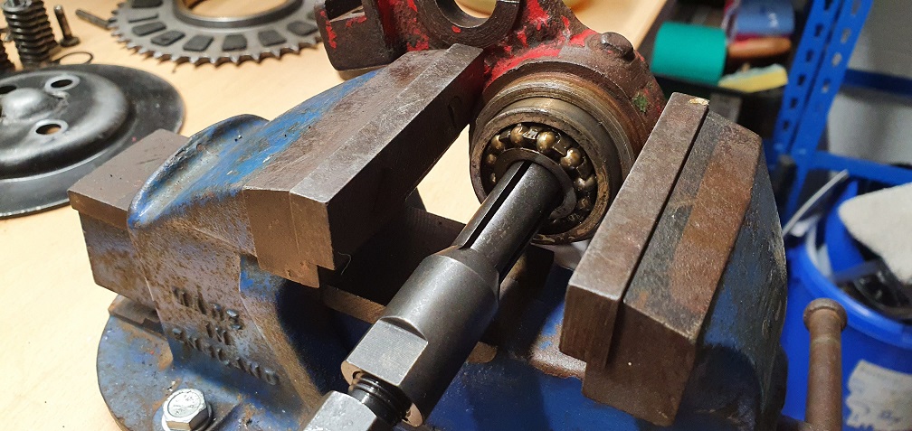
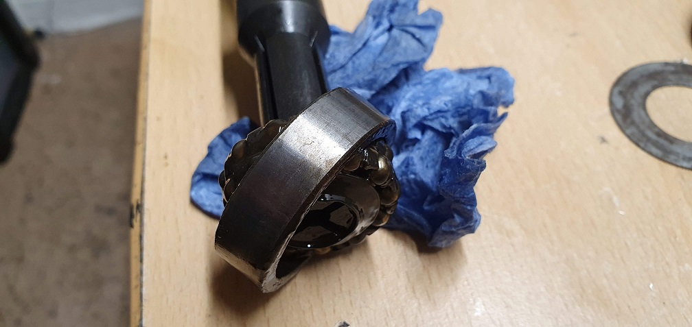
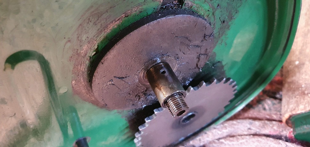
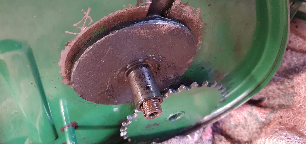
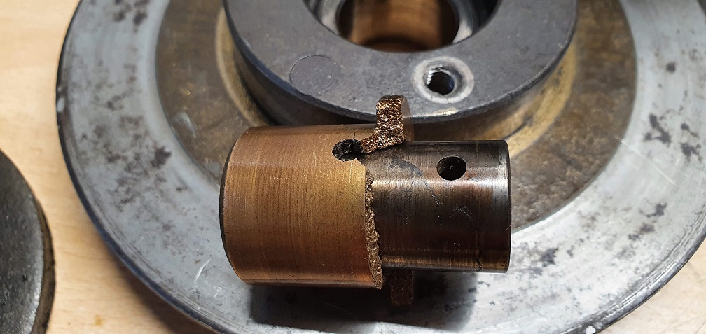
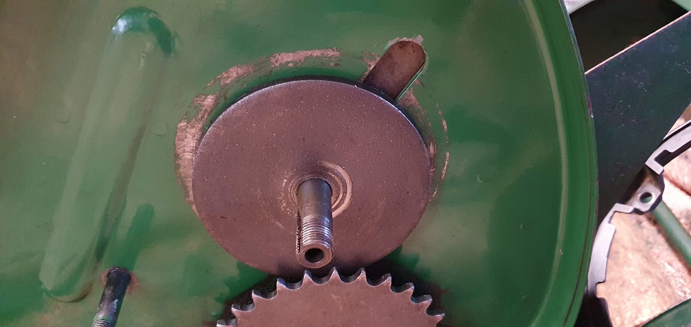
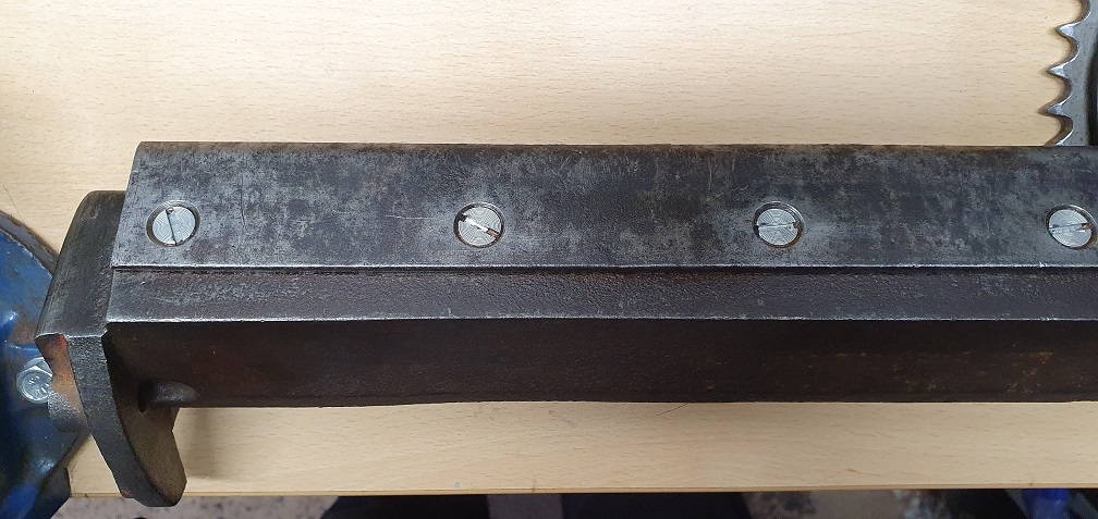
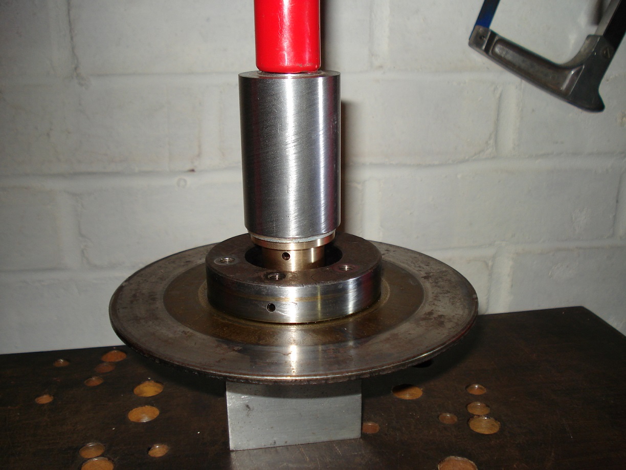
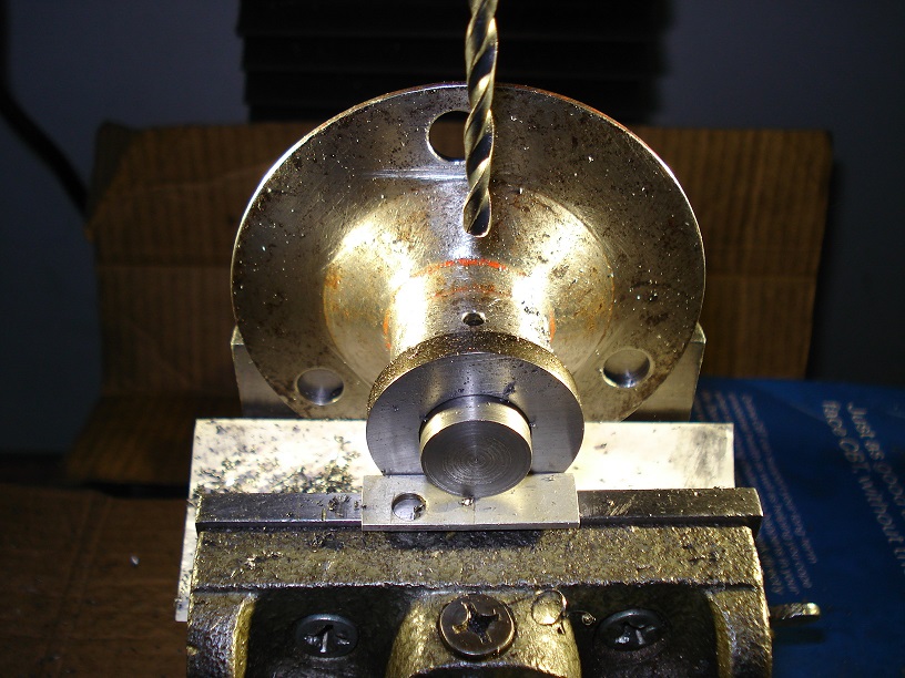
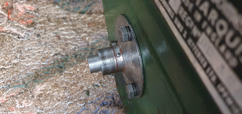
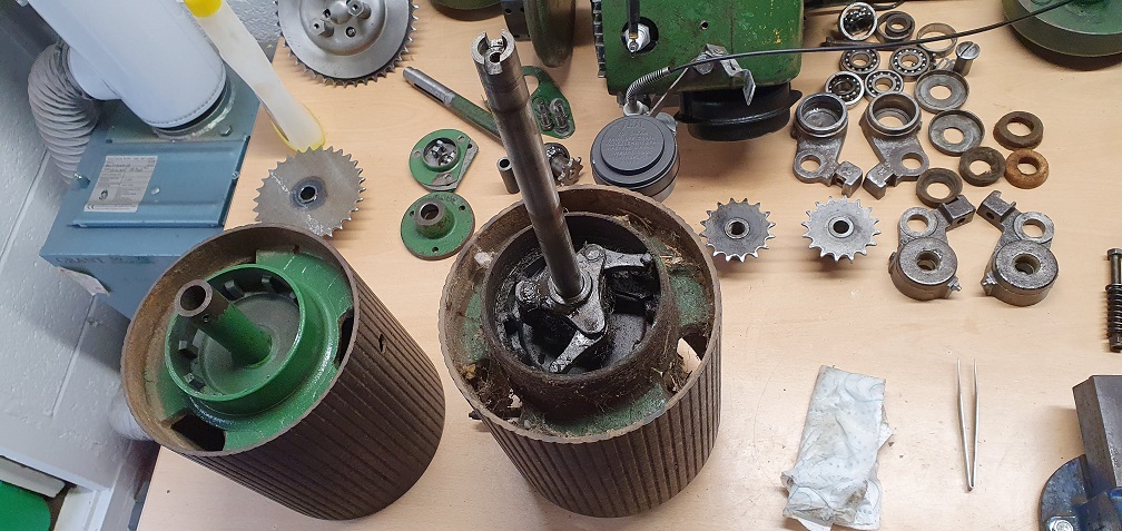
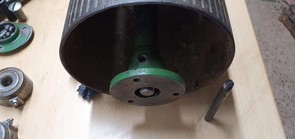
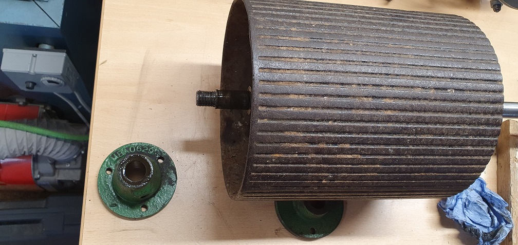
Meanwhile, I popped to the local garage with the stubborn clutch drum and shaft after several days of soaking and not getting it to budge, and they kindly pressed the shaft out from the drum for me - here's a picture showing the rust which was the cause of this being my nemesis for the past week
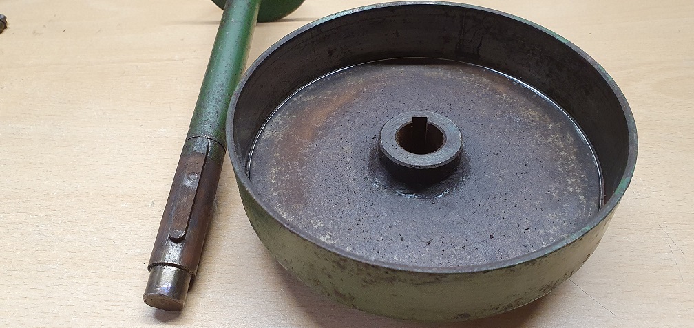
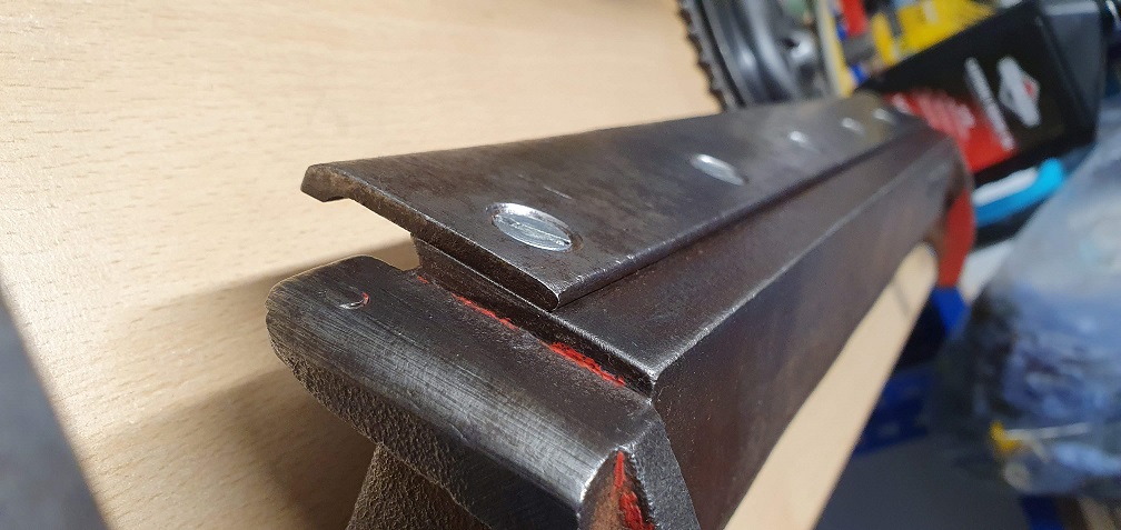
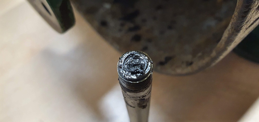
Easy with the right tools. However this did leave the spigot end of the shaft with a very slight mushroom
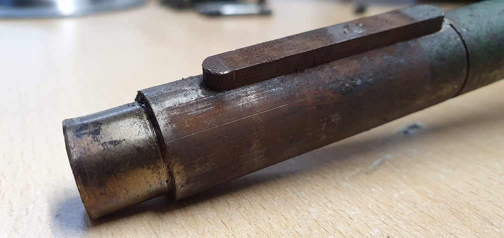
Thanks to Hortimech for the vice suggestion for the clutch drum key removal from the shaft. They both took some soaking for a couple of days with plug gas beforehand to assist, however with some lifting grunt, both keys were removed cleanly and remained unscathed thankfully
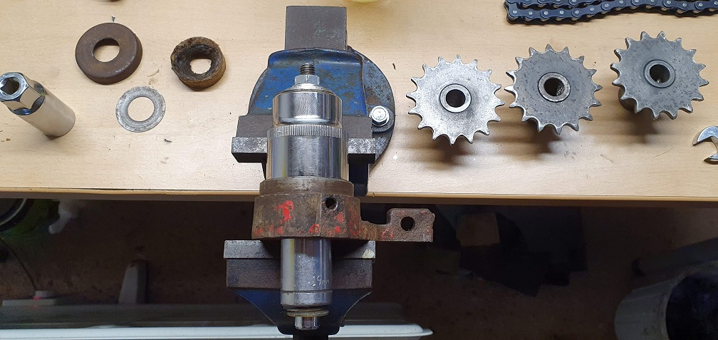
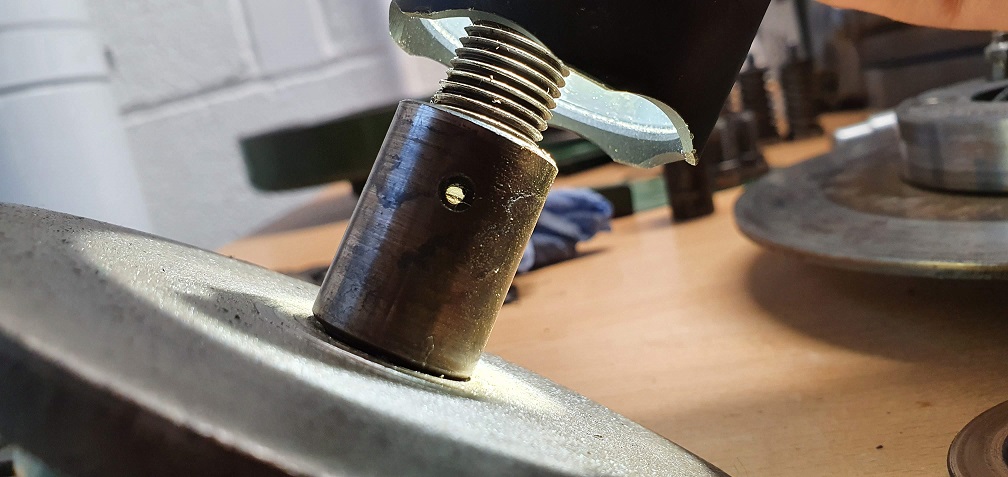
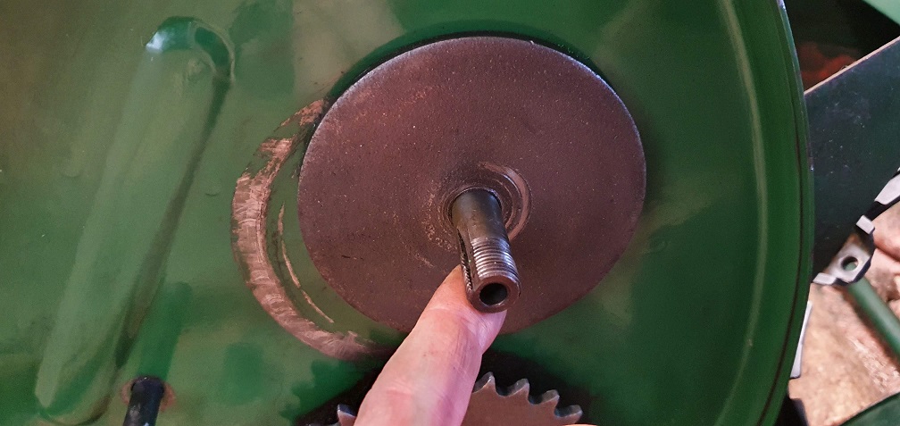
As there was no bevel on the end of the shaft, I hoped I could eliminate most if not all of this slight mushrooming by creating a bevel - which would also assist in reassembly into the bearing when the time comes. After a clean up
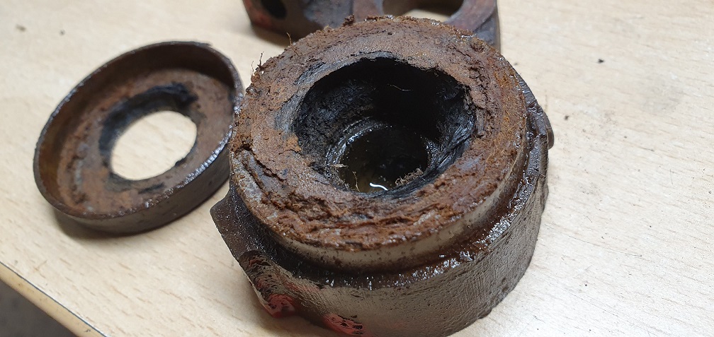
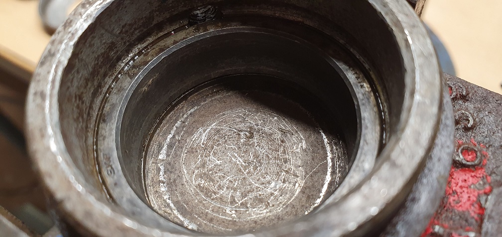
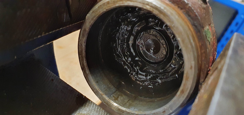
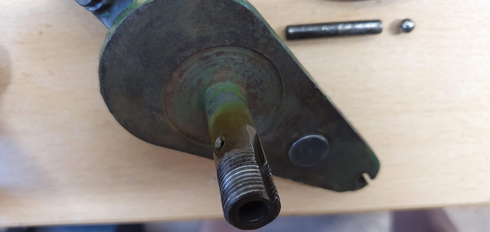
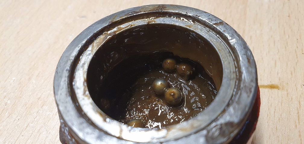
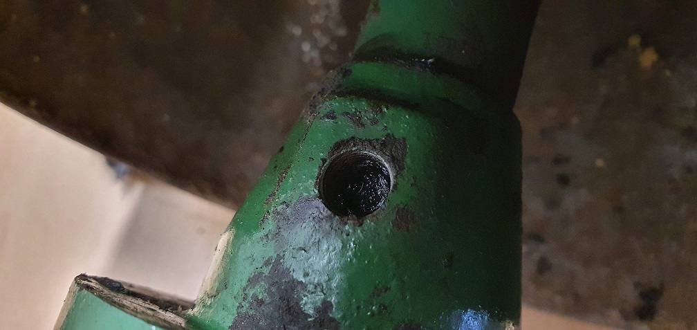
The lubrication nipple removal at the other end of the shaft exposed more dry hard grease down in the hole as well as the passageway up to the bearing, so all received a good clear out
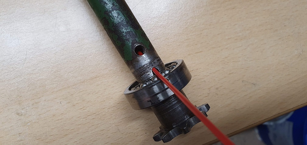
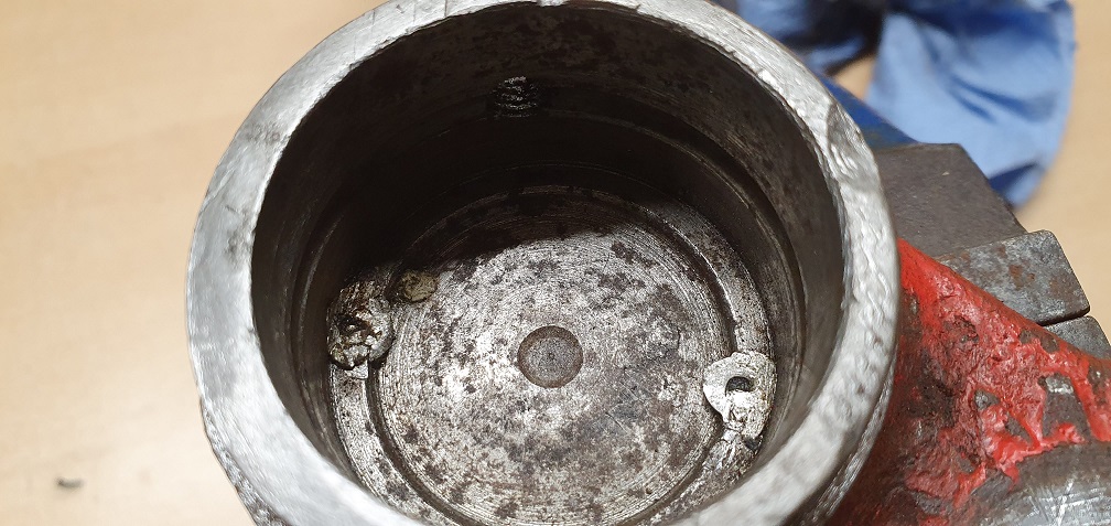
Lots of metal shavings inside the hole as well, which were probably from the original thread tapping - retrieved with a small magnet tool
I could now see the 'stepup' at the end of the oilway that Wristpin mentioned, which the inside race of the bearing sits against
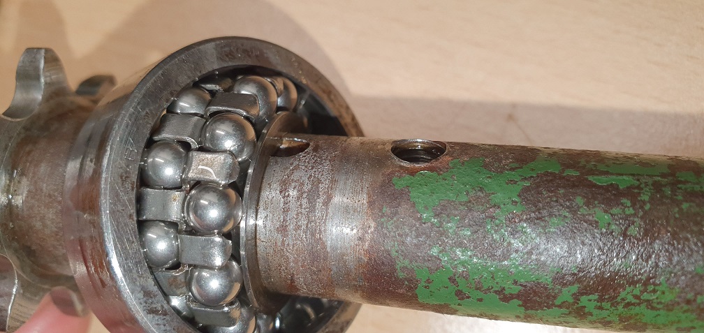
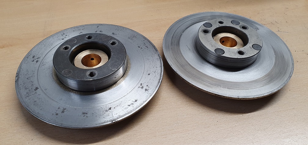
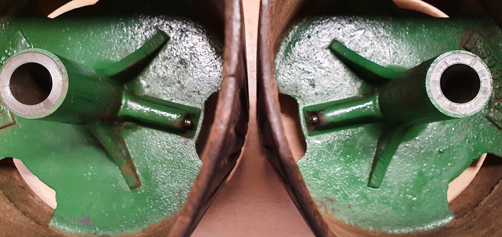
As the drum slid off from the mk4a clutch shaft easily, and the key was removed using the vice again, comparing the 2 clutch shafts showed that the keyway was milled in a different location in relation to the lubrication nipple
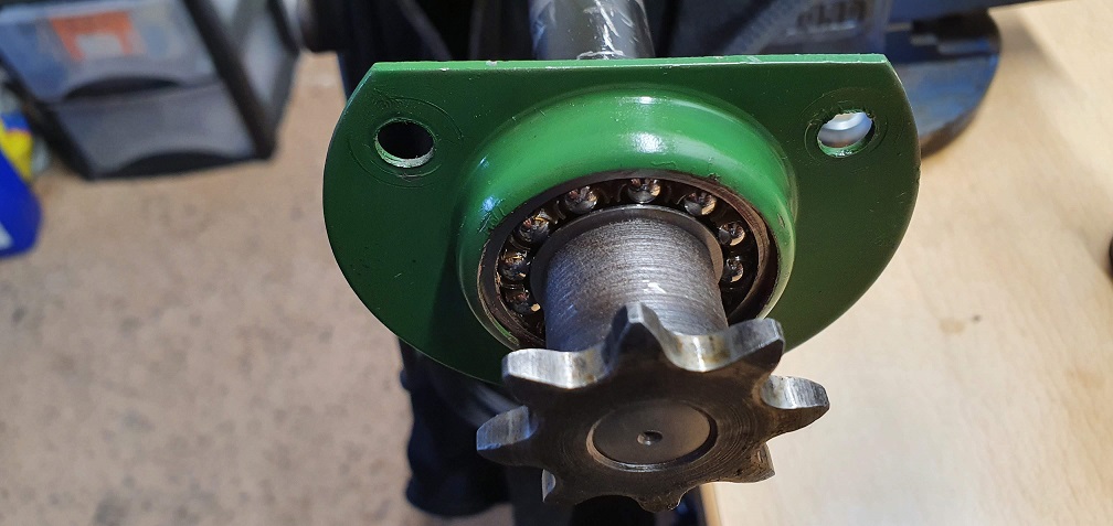
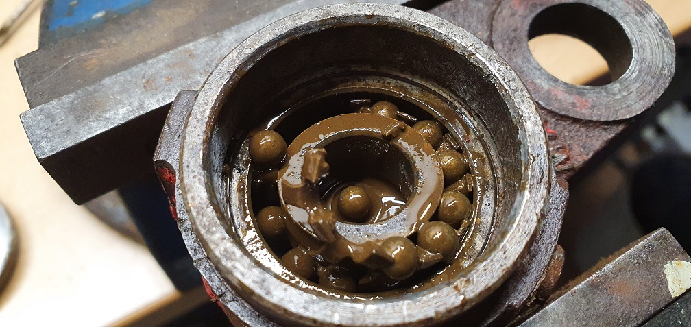
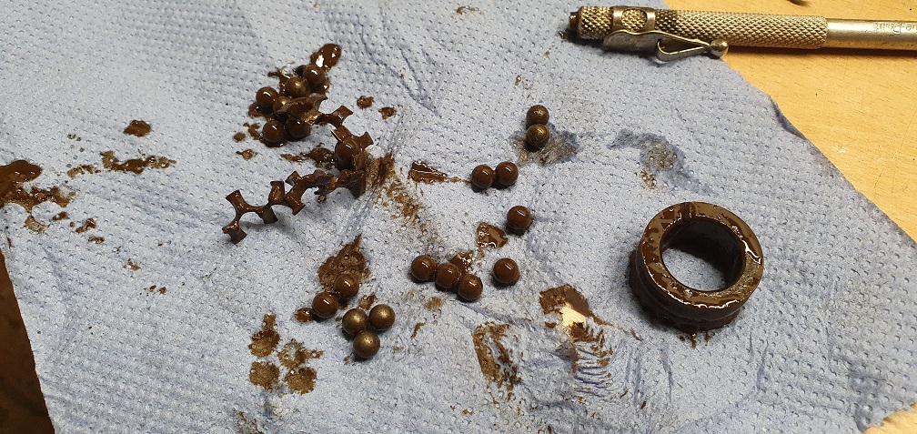
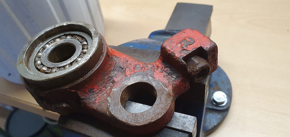
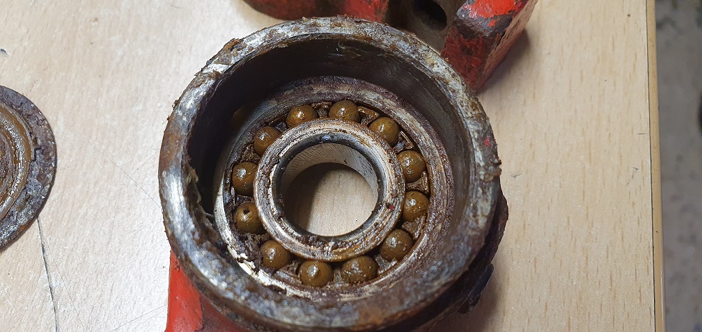
Both of the RL5 bearings are pretty rough when spun, and one ball fell out of one of them, so probably both due for replacement.
Next jobs will be creating a chain tool to remove the sprocket from the ends of these shafts, and then I'll have to either buy or try to make a clutch removal tool for the clutch centre nut on both mowers
Might have been easier to
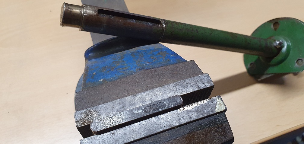
Might have been easier to remove the sprocket while the shaft was still in place supported by the side plate and engine but now, perhaps replace the big key and hold the shaft in the vice with the key positioned to resist rotation.
If you are going to make your own clutch tool , bear in mind that the manufactures original design allows for the chains to be adjusted with the clutch fully assembled rather than “a lesser tool “ that may require the sprocket etc to be held in place on the hub while tensioning the chains and doing the nut up..
When it comes to getting the correct tension on the chains , some days it’s easy, on others it fights. It only needs a little bit of run out (wander!) on the cylinder shaft to make the operation one of compromise.
,
Thanks, I'll give the
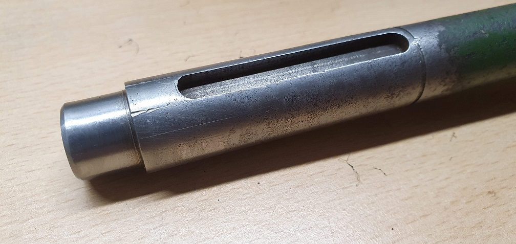
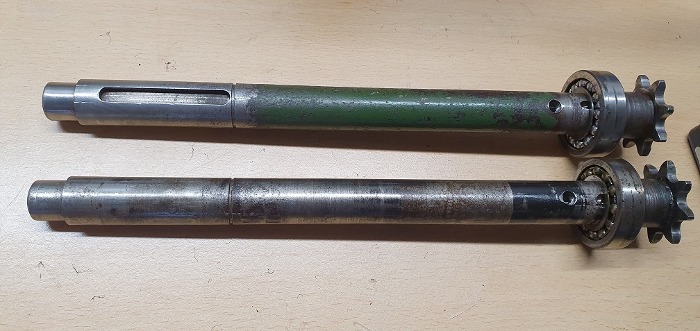
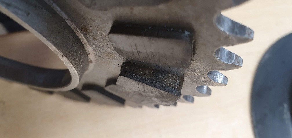
Thanks, I'll give the sprocket removal a try, using the vice to prevent rotation against the key, and if that fails, I may introduce a second pair of hands and some 24" stilsons on the shaft to stop it turning. Then the bearings can be pulled off and replaced. The sprocket end of the mk4a shaft looks to have been fettled with - not sure what could have been done to it - looks almost 'trimmed down' slightly with a very uneven surface
In terms of the clutch tool, I've been on the look out for one - saw one in a job lot of Ransomes tools on the bay not long ago and wish I'd bought it! I've got the dimensions and some pictures of the correct tool, so could see about getting one made, but I doubt it would be any cheaper than getting one from a Ransomes dealer - I'll get a price.
Some more differences between
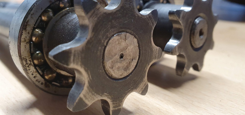
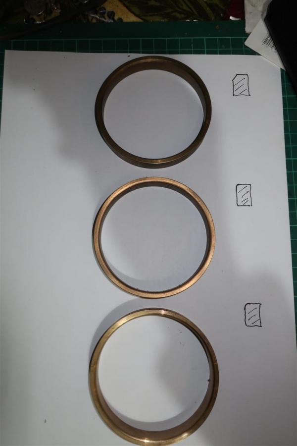
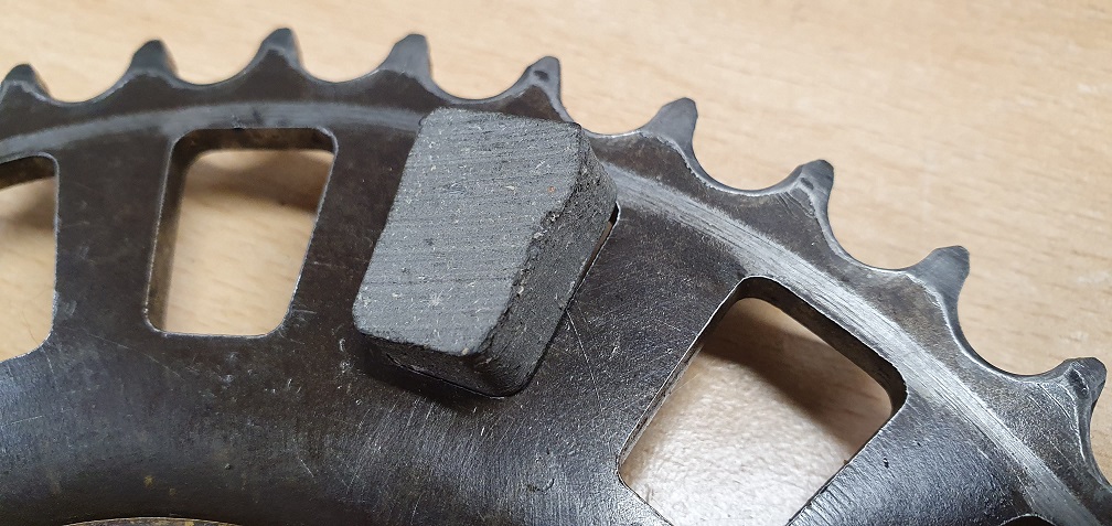
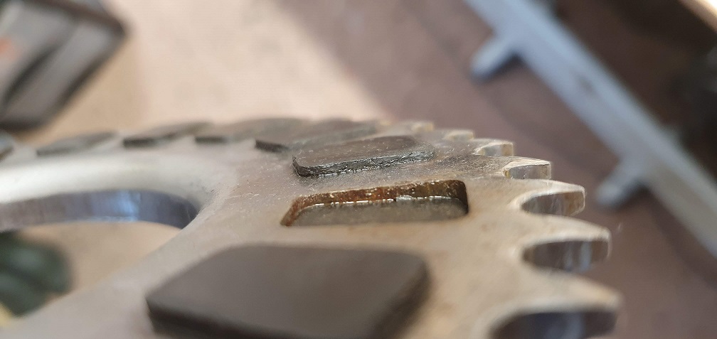
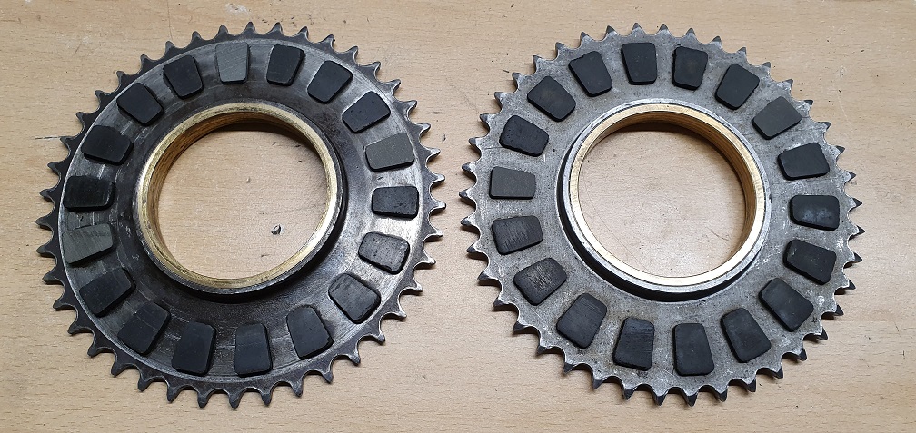
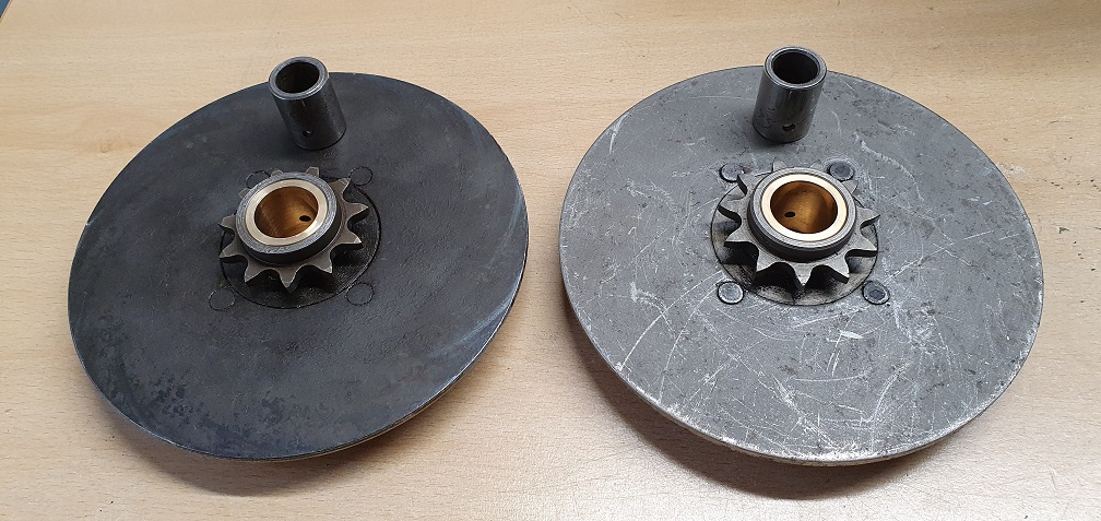
Some more differences between my two mowers - not saying that these are definitive differences between the mk4 and the mk4a, simply showing the differences between the two in front of me as I've found them. The Intermediate chainwheel has a slightly different appearance - the mk4a on the left and mk4 on the right. Perhaps just more wear on the older mk4 one
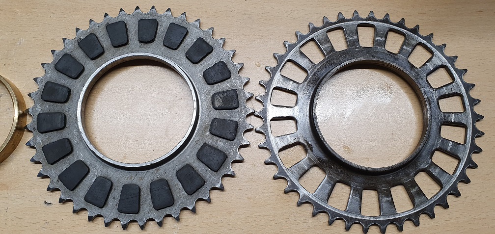
The individual pads don't seem to want to move at all on the mk4a wheel - should they be free to move in and out (completely) as per the pads from the mk4 wheel that all came out freely? There aren't any lips or angles to the sides of the pads which would retain them in their holes.
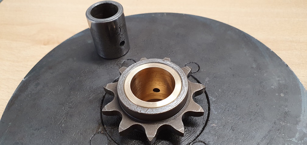
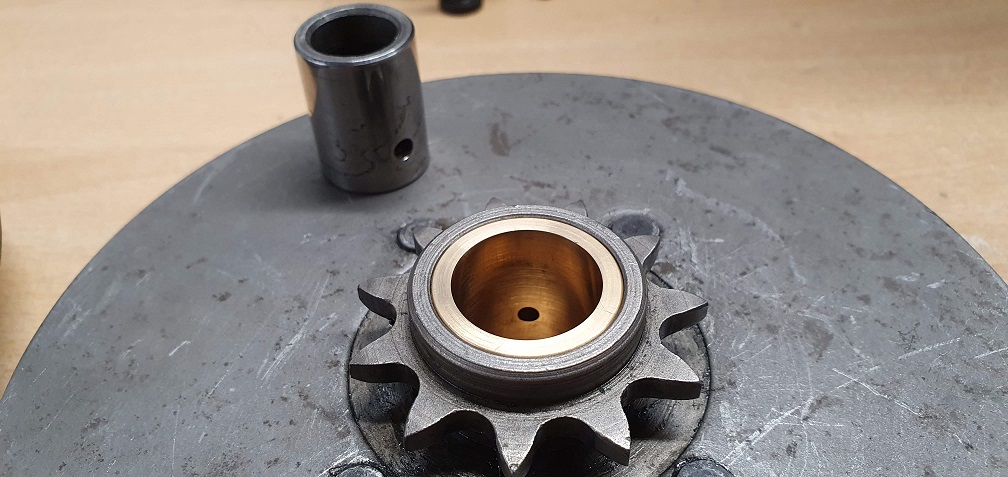
The brass Intermediate wheel ring bush from the mk4a has a bevel on the back edge, and this isn't present on the one form the mk4
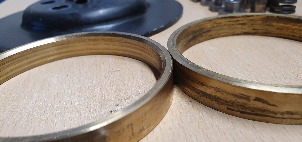
Are these brass bushes supposed to be a press fit into the wheel, or are they designed to simply fit into place? Should they be able to rotate inside the wheel when fitted or be stationary? The mk4 bronze bush fits into the wheel from the front side easily and has the tiniest lip on the upper rim which prevents it from going past 'flush'. The mk4a bush feels like it needs tapped into place in the wheel and is a much tighter fit
I would venture to suggest
I would venture to suggest your CSI examination of the two machines is interesting but misguided. You are looking at machines that are over fifty years old, will possibly have been through the hands of several owners and repair shops and may originally have been assembled with parts made by different outside suppliers ; or assembled in their entirety by a subcontractor.
Additionally components such as that large ring bush may have been machined way before the days of even the crudest automated machine tools and providing the critical inner and outer dimensions were correct the final finish - chamfers etc - may have been down to individual operators.
I think that your observations are interesting but not untypical of pre CNC manufactured components. Possibly not relevant to this situation, thirty years ago I had a pack of five cutter spindles for a UK made mower with a a difference of 5/16” between the longest and shortest - yes, you read that correctly. 5/16 of an inch.
Back to reality - that top shaft looks as thought the end has been attacked with an angle grinder. Quite why , we will never know.
EDIT
Three new LCG1453 bushes . Each with a different chamfer on one side. Flat angular, tight radius and rounded radius.
Apologies for the image quality but a quick snap on the kitchen table!
SECOND EDIT! Clutch peg spanner LCG1491 £36.04 inc vat retail.. £25.53 + vat trade
Interesting to see the
Interesting to see the differences in the bush manufacture, and thanks for the clutch peg spanner price. I'm not sure if i have the tools or materials to come up with a suitable home made job so may have to resort to buying a genuine tool.
Regarding the brass ring bush - should that be a tight press fit into the intermediate wheel housing?
The clutch pads that sit in the intermediate wheel - should they be free to move back and forth in their hole between the plates when in position, or should they be fixed centrally in their housing? Just understanding how it works as i haven't seen it in action yet as such. If the don't move freely, and some happen to be stuck, would the plates only grip where they both make contact with each side of the pads?
The ring bush is no more than
The ring bush is no more than a light interference fit. If you put it in the freezer for a while it will just push in by hand. If it’s loose, a drop of Loctite will do. Nothing too powerful , blue thread/ stud lock is fine.
Clutch pads seem to vary in fit but I think that they sometimes swell with use. I usually centre them up. I can’t remember ever seeing them worn out.
Thanks, a drop of blue
Thanks, a drop of blue loctite is in order for the bush on my mk4 in that case - with a trip to the freezer for the other one!
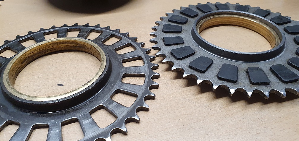
Regarding the clutch pads, it seems that the wear that is present on my mk4 is around the sides of the pads as opposed to the depth of the pads, resulting in the pads not being held in the wheel at all. I don't see this causing a problem in the function of the clutch at all. When compared with some new LCG1452 pads that I bought to replace the missing or damaged pads, the size difference is apparent
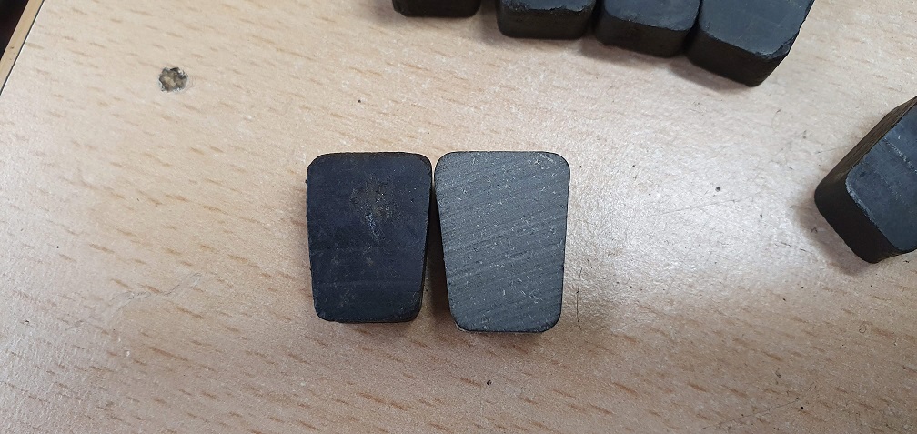
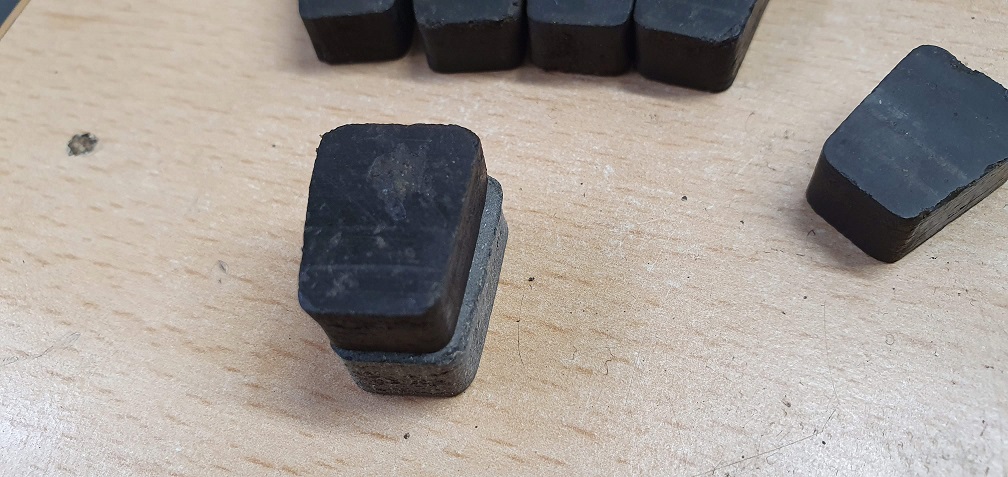
The old pads are near enough the same thickness, indicating very little wear. The new pads aren't interested in fitting into the cutouts in this wheel, so I may need to dress the sides of the pads very slightly to ease them into the wheel. The new pads are much more like the size of the pads on the mk4a wheel that I have, which may well have been a replacement at some point in it's life, and as such, presently displays less wear. The pads on the mk4a wheel I have are very tight in their cutouts - it appears after gently trying to free one up that there is a little bit of corrosion around the wheel cutout edges, which combined with some swelling of the pads during use, has made them quite static. I'll see if I can get just a little movement on them with some lube and gentle taps, just enough to get them centred.
I see what is meant by 'tight
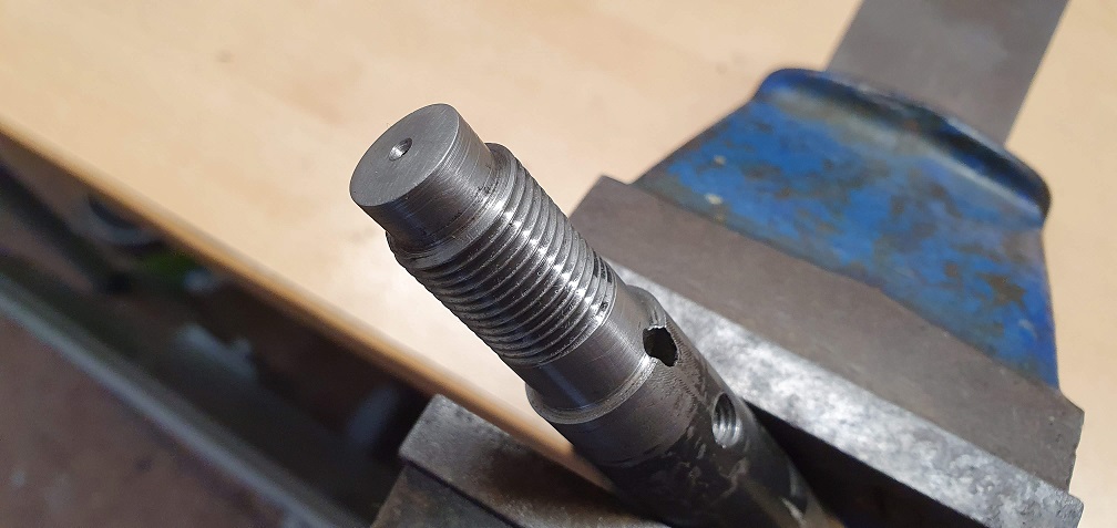
I see what is meant by 'tight' when people refer to this clutch shaft sprocket removal - a can of spinach beforehand helps to persuade it off
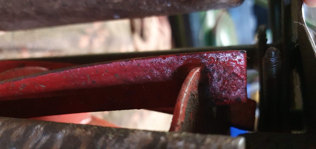
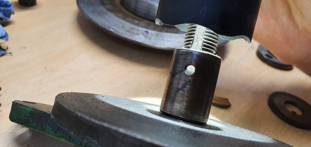
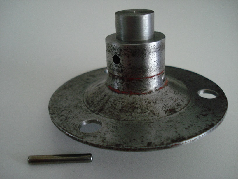
and the other shaft where the end of the shaft has been attacked for some reason in the past
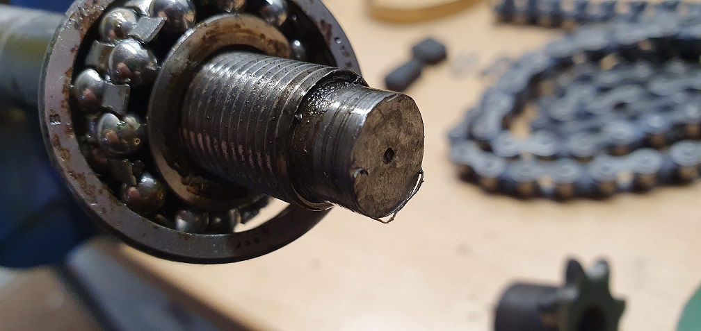
Only the chamfered end of the shaft has been 'removed', no idea why
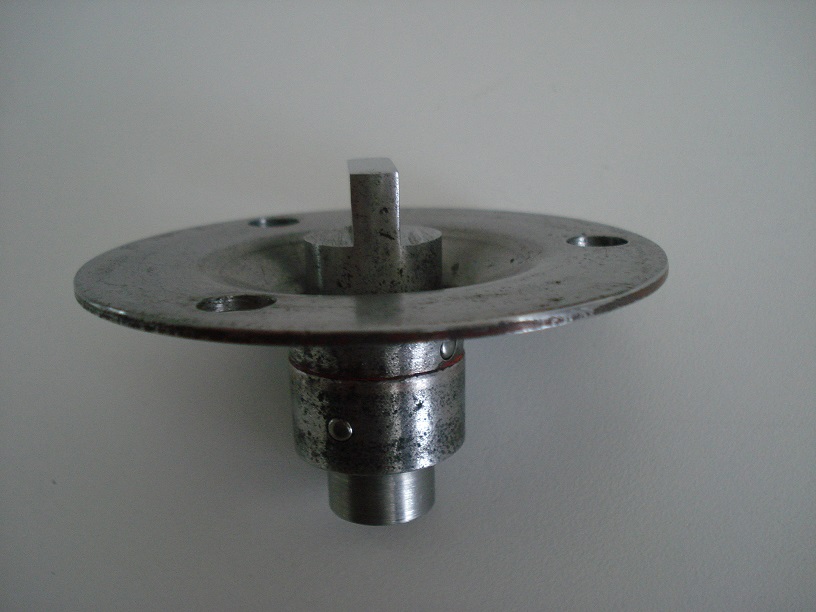
so I tidied up the end a bit
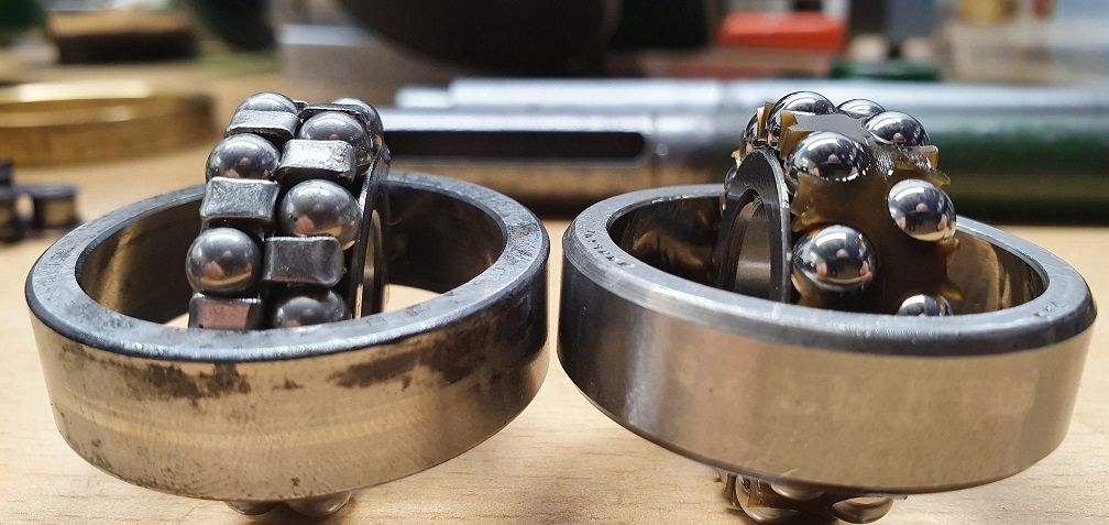
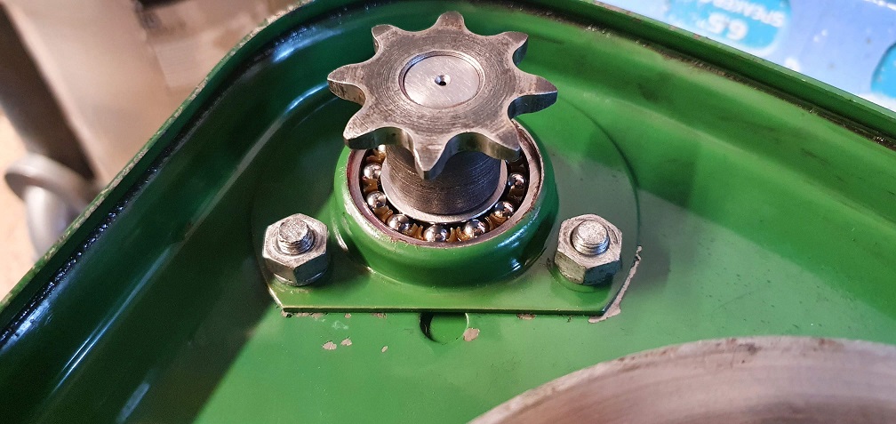
RL5 bearing replacement
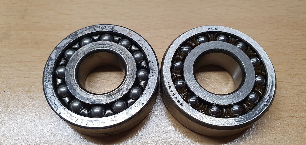
Plastic ball cage in the new ones and silky smooth
Onto the cutting cylinder drive chain next - a good cleanup and degrease to examine for any stiff links. Unfortunately a number of plates and rollers with corrosion on the mk4 cutting cylinder drive chain
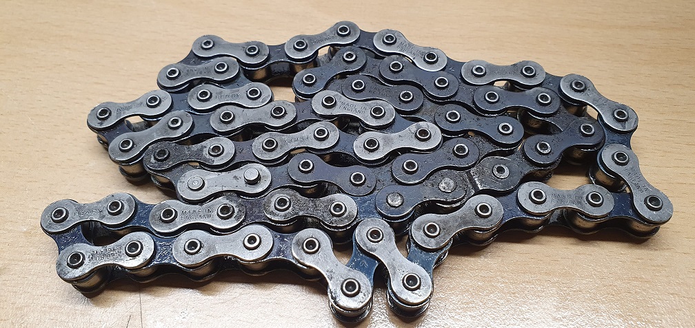
Probably past it's best anyway, so this one has become my spare bit of chain, which I didn't have any of, and assisted in the removal of the clutch drive shaft sprocket, so it lives on serving an alternative purpose!
The cutting cylinder drive chain on my MK4A is in much better condition with no corrosion at all
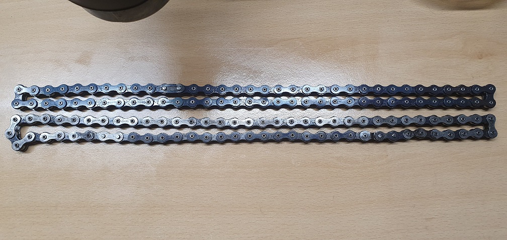
I noticed that the MK4 chain was slightly longer than the MK4A chain. Looking at the part number, 111049 / 68, the 68 appears to refer to the number of rollers in the chain. I say rollers, because dealing with pushbikes over the years, I'm used to calling a 'link' a pair of inner or outer plates. So I initially counted 34 'links', which is 68 individual rollers.
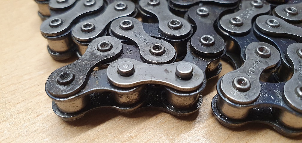
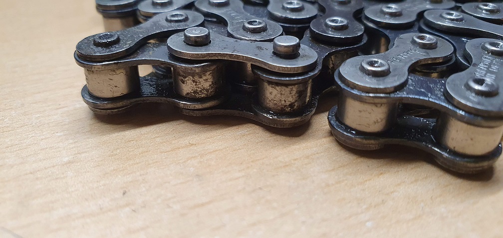
So my MK4 chain has 1 extra roller, obtained via the use of a 'half-link' where the outer plate of the half-link outer plate reduces down to an inner plate where it joins the next roller, as can be seen here
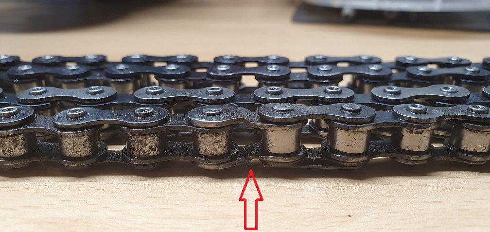
so I'm wondering if someone has maybe removed a section of even worse chain at some point in it's history and added in some replacement links, making the length what they thought was 'near enough'. Alternatively perhaps the additional roller was added in if the cutting cylinder adjustment was getting towards the end of it's usable travel, due to the cutting cylinder wearing down in diameter, and making the chain too tight perhaps. Complete guesses here, perhaps it doesn't even matter, just my curious mind mulling over 'why?' as it tends to do with everything....
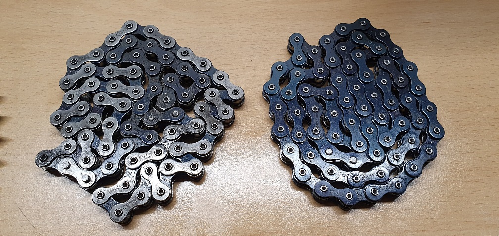
So some new chain needs to be ordered. The pitch is 1/2" and when searching online suppliers, I'm faced with the majority of measurements being in metric strangely, but I've taken measurement of the roller diameter and width as well as the plate thickness, pin width/diameter etc so hopefully can find something suitable. The landroll drive chain, part number 111049 / 39, looks in good condition on both mowers, so possibly renewed at some point in it's life. This chain, on both mowers, is the same length, and includes a 'half-link' as I would expect, to achieve the 39 individual rollers.
I noticed that the MK4 chain
I noticed that the MK4 chain was slightly longer than the MK4A chain. Looking at the part number, 111049 / 68, the 68 appears to refer to the number of rollers in the chain
The normal way of specifying the length of simplex chain is in "pitches" . The pitch being the "hole" between the rollers. Hence the hand written note on one one of my parts lists is "Main chain, 68 P including connector" and "trans chain. 40P". I'm not sure whether this equates to your findings or is even correct. Atco always used to give a part number and pitch count for the chain and a separate part number for the connecting link. I'll have a count of the chains on the machine that I'm working on at present. The original Marquis sliding traction clutch assembly does give a considerable amount of adjustment in both directions , and while getting both chains satisfactorily tensioned can be a fiddle, I have no recollection of ever having to lengthen a chain to accommodate cylinder and bed knife wear. However the later design of Marquis and Super Certes etc were actually actually supplied with a cranked link (note, NOT half link) in the operators manual pack. I've just fitted a new cutting cylinder to a Super Certes and had to remove said cranked link from the chain to reduce its length by "one pitch" to obtain satisfactory tension.
You comment about the difficulties caused my metrication . I came across this recently when my favoured chain supplier, Simply Bearings, who are normally very good, just couldn't get their combined heads around being asked for half inch three sixteenths chain. It does seem that the number of staff in such establishment who understood imperial chain sizes, is dwindling fast; perhaps we need to seek out suppliers who are used to dealing with vintage motor bikes etc. The situation is made worse by nearly all run of the mill chain being made in Poland or India and other far flung places Even the good old quality British Renold chain is, I believe, now made in foreign parts.
The '68' in the part number
The '68' in the part number for the cutting cylinder chain ties in with the number of roller pins I count on my mk4a chain, which is the same as the number of holes or 'pitches' in your notes. The 39 in the part number for the landroll chain also ties in with the number of roller holes/pitches in the chain on both my mowers. Interesting that your notes have 40 pitches for this chain though.
I did spot what appears to the be correct spec roller chain on the Simply Bearings website, titled 083-1 BS Narrow Section Simplex Roller Chain 1/2 inch Pitch. The roller diameter and width match up with my measurements - I'll need a suitable chain link to match as the one on the worn chain I am replacing is loose and doesn't grip the pins well at all.
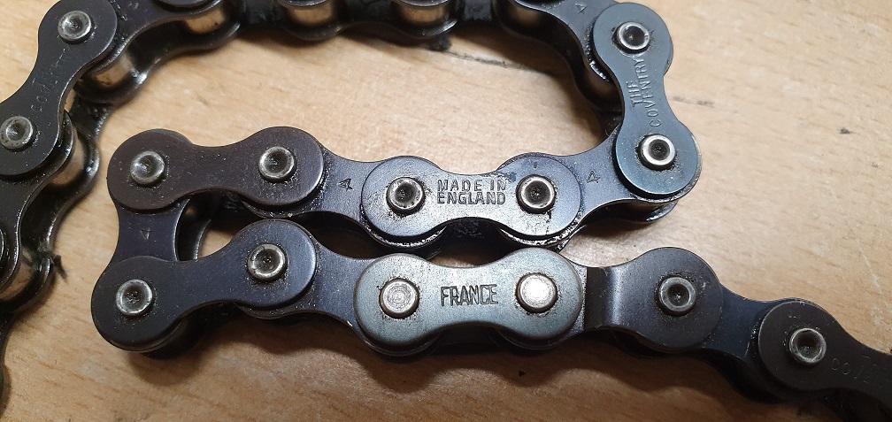
A picture of the landroll chains from each mower - one TYC made in Taiwan, the other made in England, with a French connecting link :)
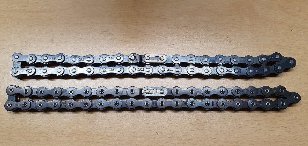
So out of the 4 chains, only one needs replacing.
Back to the clutch pads, it didn't take much to shave a fraction off the sides of the new pads to get them to fit snug into the intermediate wheel holes, so I now have 2 complete wheels with no missing or badly damaged pads - 3 new pads on one wheel, 2 new pads on the other, replacing the most worn pads. The freezer trick done the job on the tight fitting brass ring bush as well, thanks for the tip
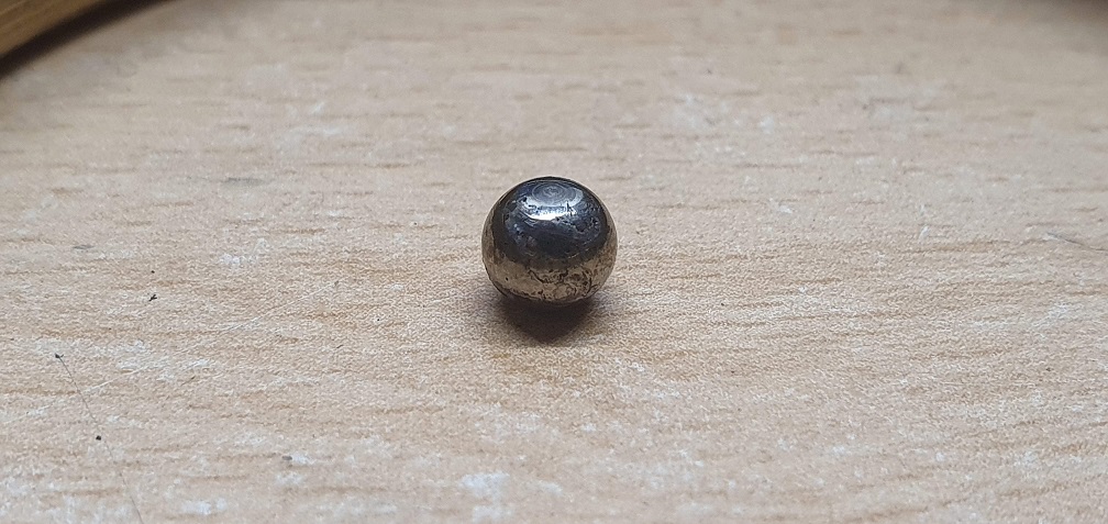
The steel ball that sits in the middle of the clutch operating mechanism, between the operating rod and the flanged rod, on the older mower has 2 distinct flat spots on it, so I'll replace that with a new one
First of the new RL5 clutch shaft bearings in place and sprocket back on the end
The 'distance piece' / spacer for the chain case cover is missing on both mowers, so I'll see if I can source replacements - part LCG 1033 - failing that I may need dimensions (please Angus, or anyone other Marquis owners reading this) to get a couple made.
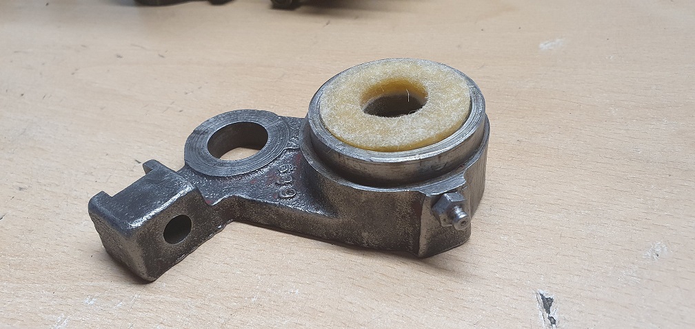
Telescopic clutch shaft guard cleaned up a bit, and ensured the felt washer was present between the clutch shaft plates before fitting
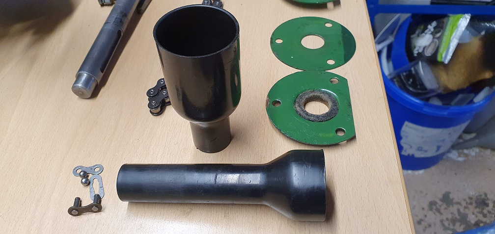
Until I get my hands on a clutch tool, I can continue with the cutting cylinder removal
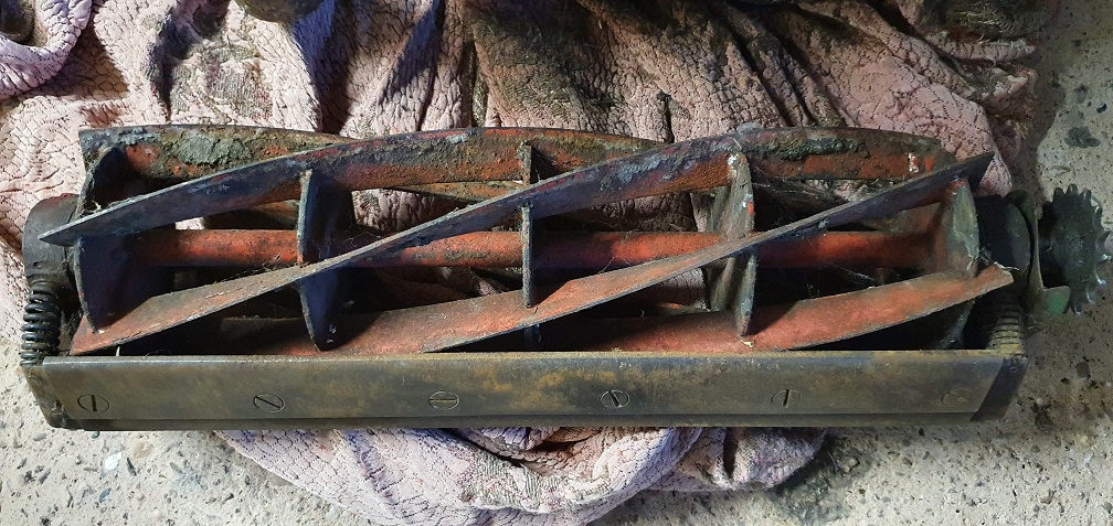
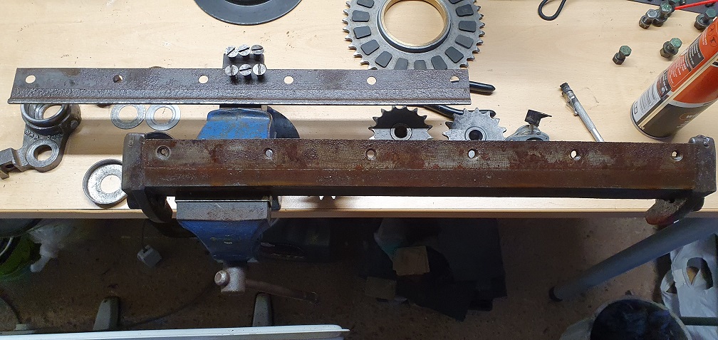
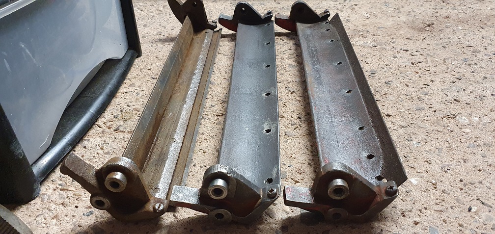
A picture showing the cutting cylinder / bottom blade on both mowers including a spare cutting cylinder/blade unit that was thrown in with both mowers when I bought them
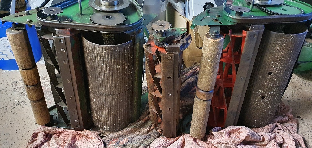
This has thrown up a couple of interesting things. The MK4, seen above on the left, appears to have either an extremely worn, or incorrect bottom blade - as there is no pronounced lip on the cutting edge, it lust looks like a flat blade - perhaps off a different mower? Hopefully someone can identify this
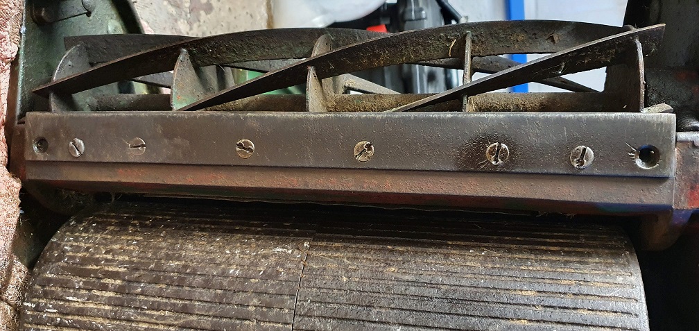
Plus the 2 end screws have been fitted further inboard for some reason, which will probably become apparent as I clean things up - maybe corrosion in the block where the original end screws should fit. As a comparison, this is the bottom blade on my MK4A
and on my spare cutting unit
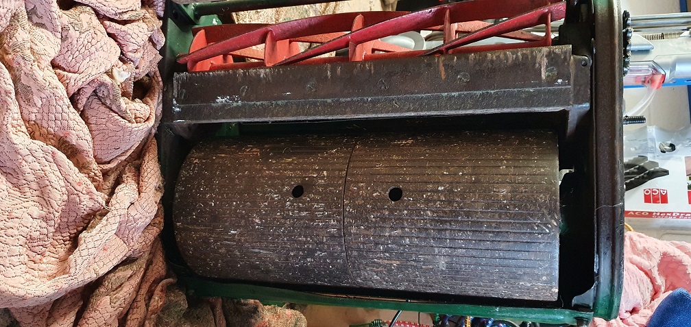
The current cylinder blades are worn down quite a bit on my MK4A as you can see here
although it was still cutting - I don't know what sort of distance form the support webs, or overall diameter is deemed serviceable, although I'm aware throwing the grass into the grass box becomes harder the mower they wear down. If it still has life left in it, as the bottom blade appears to, then it will be kept as a spare unit, and i'll fit the current 'spare' in it's place - which has more meat on the cylinder as you can see here - just needs a clean up
By swapping these out, hopefully it means I don't need to deal with the screws on the bottom blade of the current MK4A cutting unit, as they certainly look their age, and have been mutilated at some point in their lives - not sure I would have the necessary tools to deal with these currently
Strange bottom blade, could
Strange bottom blade, could be from an Auto Certes, they are flat, perhaps it was fitted to get a closer cut. Why were the original outer mount holes not used ? are they stripped ? If so, then depending on the material, you may be able to weld them up and then redrill and re-tap them, otherwise they will require Helicoiling. If they are blocked with sheared screws, then I used to heat the broken screw (red hot) with a welding torch and the punch them out with a drift.
An impact driver is the tool
An impact driver is the tool that most mechanics use in such conditions, looks like someone already did. You probably know what I mean, it's a chromium plated tool about six inches long that comes with a good selection of screwdriver bits, you hold the correct bit already in the tool tightly into the screw slot and wallop away with a suitable large hammer, I use a copper faced one and my I.D is still like new 20 years later. Don't forget to take up any slack between blade and slot and tool, or most of force can be lost. Heat and penetrating oil, a god walloping of an ordinary screwdriver into slot first will usually pay good dividends. These tools can undo and do up tight screws nuts bolts etc. make sure it's in the undo mode first though!
All 20" Marquises had lipped
All 20" Marquises had lipped bottom blades with six screw holes. Auto Certes had 8 screw holes and either a non lipped grooved Standard blade or a chamfered thin edged Shaver blade.
Cylinder blade wear . A worn, reduced diameter, cylinder will continue to cut but with reduced ability to throw the grass into the box.To some extent this may be compensated for by adjusting the distance and curvature of the throw plate from the blades. Marquises have slotted and reversible brackets to facilitate this. Ransomes recommend a distance of 1/16" / 1.5mm between the blade tips and the throw plate measured behind the cylinder in line with its horizontal axis.
Screw removal. A hand held impact driver is a useful tool but in this case I think it will struggle as a result of the damage that has already been done - probably with a hammer and punch. Ideally you need access to either oxy acetylene or oxy propane heating equipment. Due to the amount of heat sink in the blade and sole plate I think that normal armature kit such as Mapp gas will struggle to do the necessary. First, if there are any screws protruding through the sole plate, grind off the protruding ends flush. Then heat each screw to cherry red and quench as you go. Then the impact driver or hammer and punch with lots of Plus Gas or even diesel oil.
In the absence of OA , grind off any protruding screws, as above. Support the sole plate upside down on something hard and heavy, and hit each screw head hard with a heavy hammer, apply Plus Gas around each screw head - at intervals, several times in the hope that it will penetrate down into the countersunk area of the screws. If you can rig up a soak tank of diesel drop the whole sole plate into it and leave it for a couple of days. Then the impact driver or hammer and punch .
Last gasp!! Mig or stick weld a bit of scrap steel rod to each screw in turn. The heat will help and the rod will turn them. Variations of this with nuts and washers etc.
Chains. Checked the ones on the machine that I have on the bench. Main, 67 + connector/joiner, 68P. Land roll drive, 37+crank link+connector. 39P. Same as yours, I think.
Thanks very much for all the
Thanks very much for all the replies and advice. I can safely say that the screw removal on the MK4A current bottom blade is beyond my means, so for now at least, that unit will have to remain dormant. It's a shame, as the bottom blade itself looks fine and would make a good substitute for the 'incorrect' blade fitted to the MK4 unit.
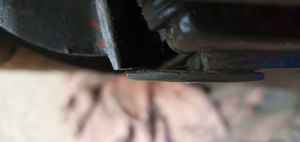
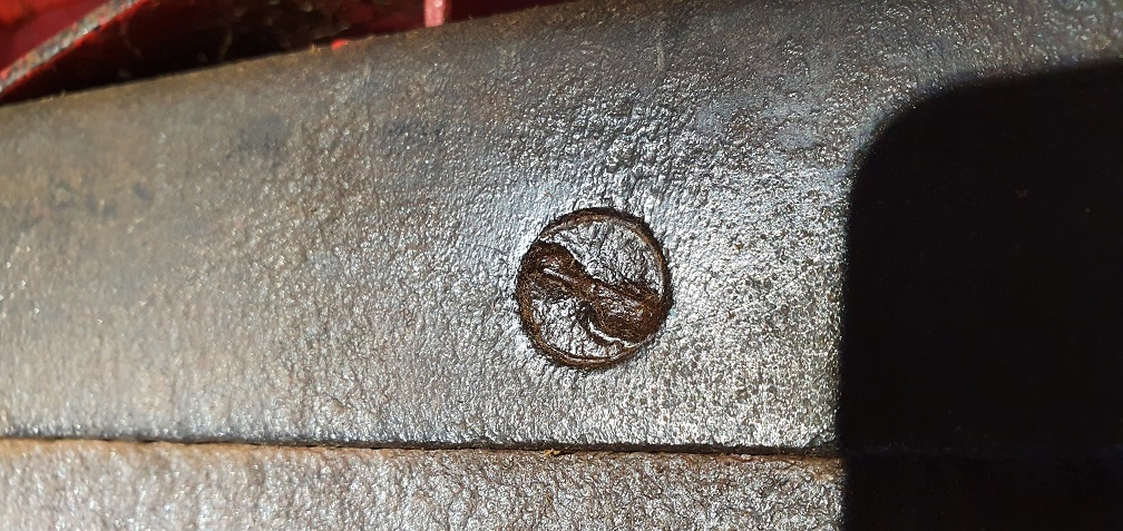
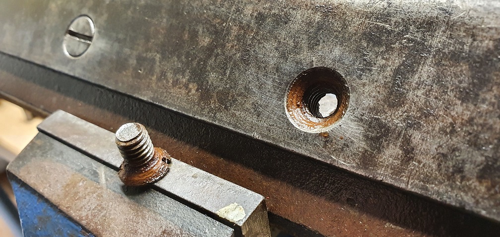
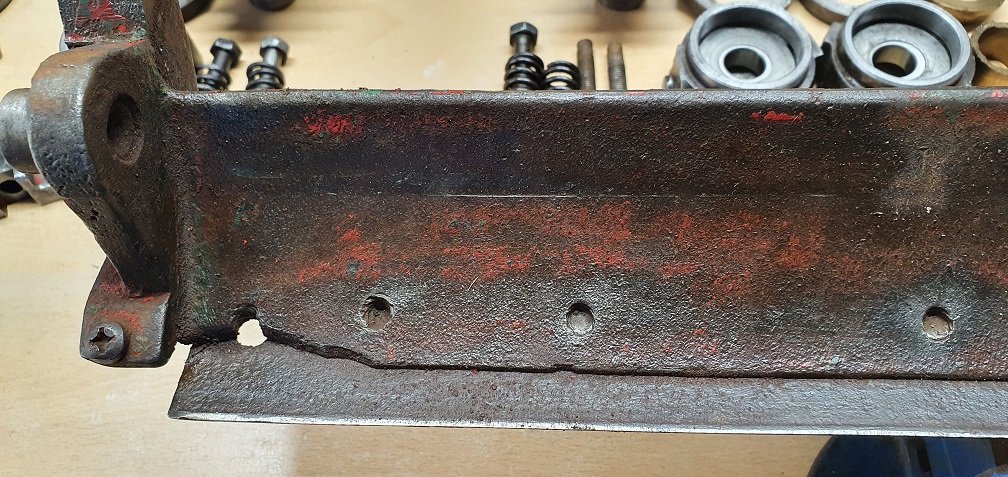
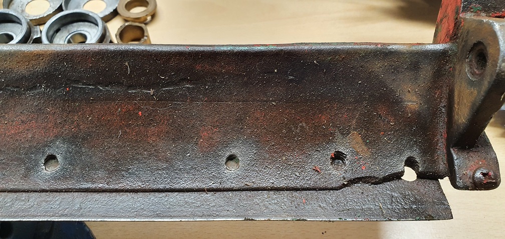
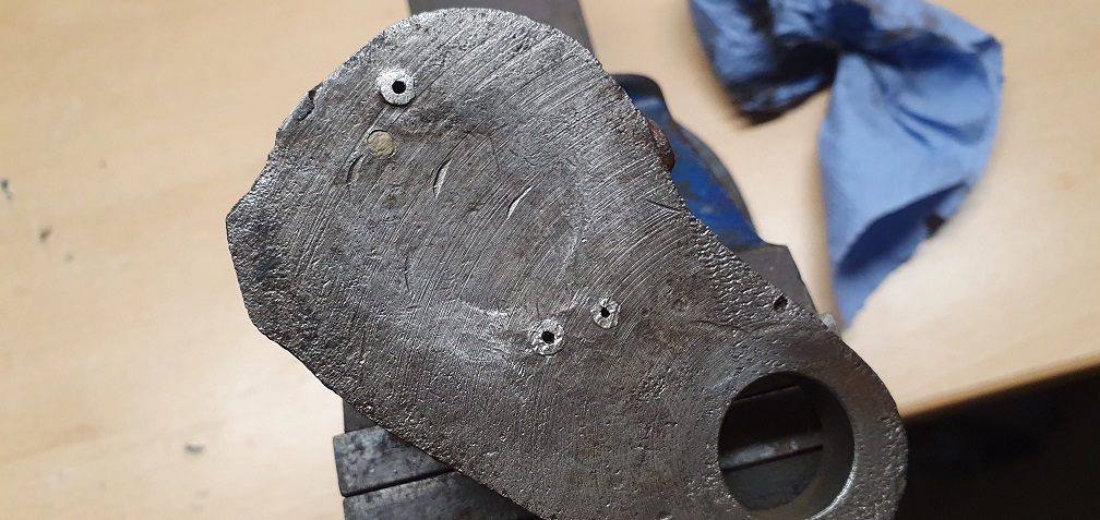
Speaking of the MK4 unit, and in answer to Hortimechs question about the outer most screw holes being vacant, I can now see why
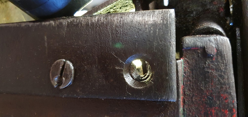
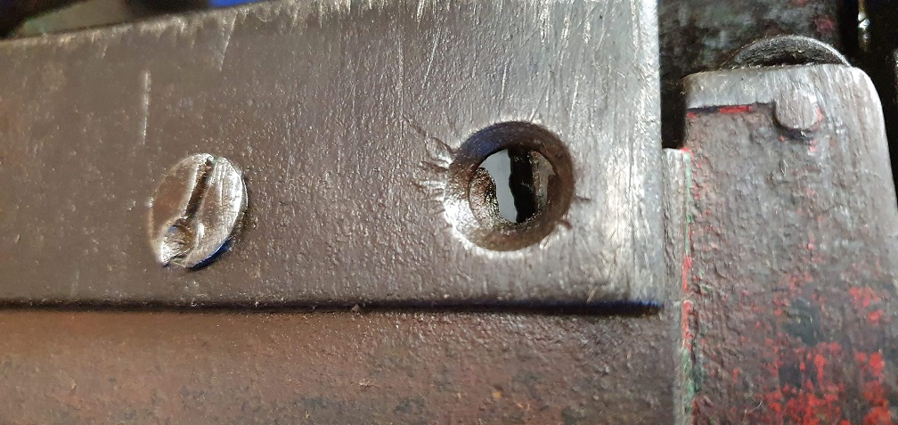
I can see the vague remains of the original threaded hole in the sole plate, but It looks like either the original screw was badly drilled out at the wrong angle, or the sole plate material between the threaded hole and outer edge has crumbled away. I'll get a better look once the cylinder is out and see what's going on at either end on the inside. If some steel could be welded into the current voids, and then a new hole drilled and tapped into the sole plate, then I could swap this incorrect blade out for the one on the spare cutting unit (if I can find someone to get those screws out) or just replace the blade with a new one with a new set of screws.
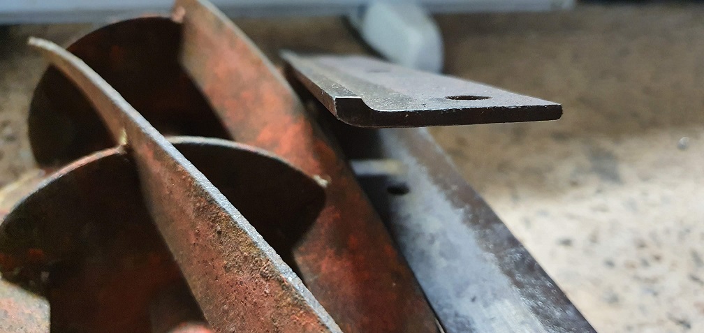
Spare unit - screws don't look too daunting
My current cutting unit on my MK4 with incorrect blade - screws have been attacked in the past - unsure if I could remove these myself
Bottom blade decent on my current MK4A cutting unit, but screw removal beyond my means
Between the 3 units I should be able to get 2 good working units with some assistance from someone with the correct heating tools or welding tools. I don't even have a MAPP torch although was considering buying one for jobs that don't have such large heatsinks. I'll crack on and get the cutting cylinder removed on each one and check the bearings out in the meantime
Angus - thanks for checking the chain links - that tallies with my findings. Although my MK4 had an extra pitch in the cutting cylinder chain - I wonder if this was to accommodate the now apparent incorrect bottom blade and the fact the cutting edge sits closer to the ground...
I wonder if this was to
I wonder if this was to accommodate the now apparent incorrect bottom blade and the fact the cutting edge sits closer to the ground...
Quite probably, as the lip on a correct blade stands quite high.
A decent welder will fill in those holes and you can screw a correct blade in place as a drilling guide, then tap the holes . Assuming the remaining screws are standard, they are all Whitworth.
Scan of a page from an old Central Spares catalogue.
https://www.dropbox.com/s/k7cwl2heo33oqzl/Ransomes%20Marquis%20and%20Au…
Thanks, I'll have a chat with
Thanks, I'll have a chat with the local metal fabricators to see if the sole plate welding is something they can help with, If I can get the current blade off - I'll keep soaking the screws on all 3 bottom blades in the meantime. The bottom blade screws have a part number LS2521/7, but useful to know they are Whitworth, so I'll hunt some out online - unless I can find a new blade that comes with screws.
I removed the cutting cylinder from the spare unit - the bearing carriers took a little effort to free up but it's a start
According to the parts diagram, there should be a felt washer, GSF3571FZ, underneath the dust cap, followed by a dust washer, LO12, and then the RL5 bearing. It's hard to see if it's just detritus or if this felt washer has disintegrated inside. It appears they are still available to buy though if this is the case. Do the outer dust caps simply pry off after a little soaking?
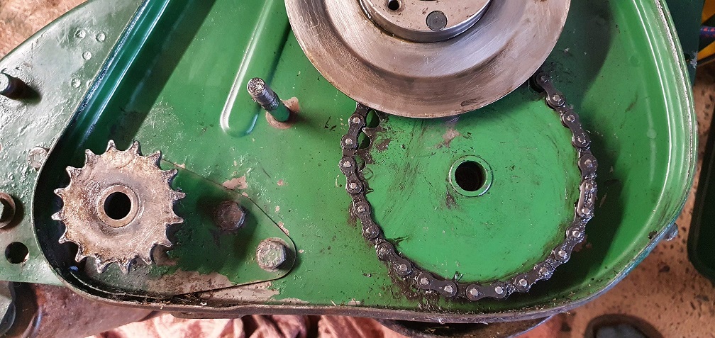
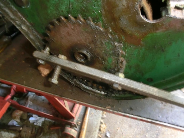
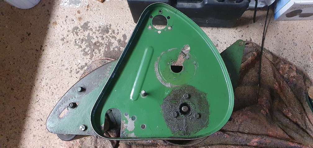
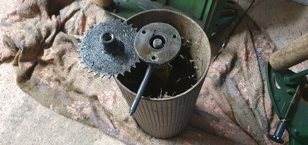
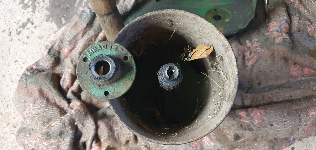
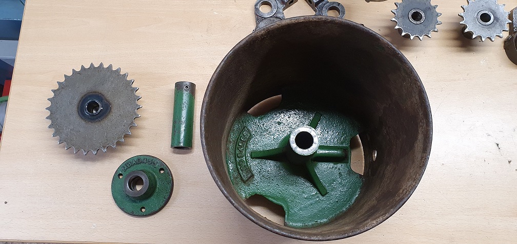
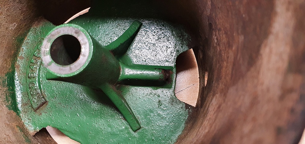
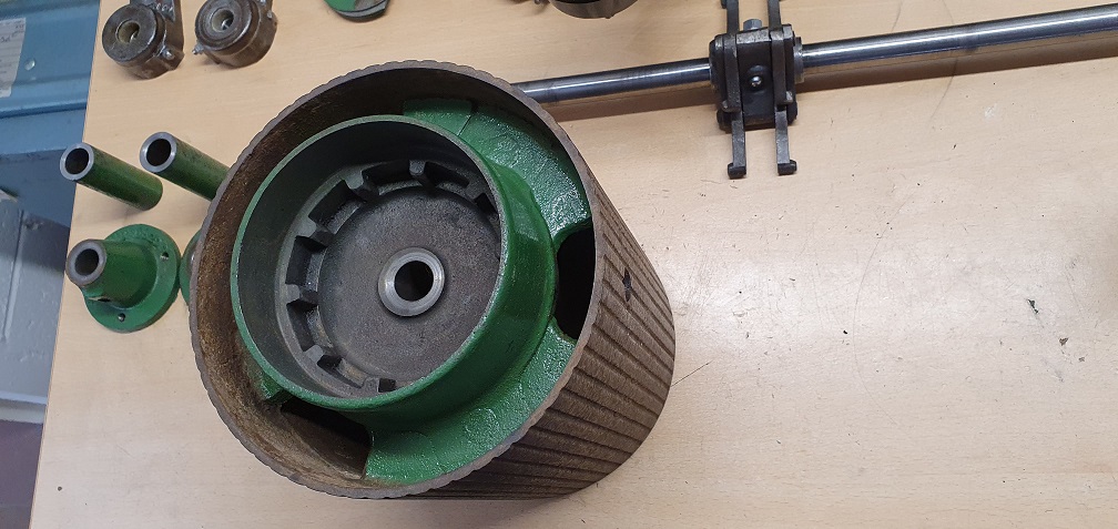
Looking at the large remaining chaincase sprocket. I'm not 100% but I have a feeling the rear roller may not be working fully on either machine, however this could (hopefully) just be my lack of understanding how the roller halves and diff work. I'm sure it's a very simple design for those used to dealing with them or similar, but my findings so far on both mowers are as follows. Both halves move independently on both mowers, which I understand is important, so nothing is seized. The MK4A takes a little more effort to rotate using the large sprocket than the MK4 - just feels like it has a lot more grease inside the internals perhaps, as it feels 'sluggish' when rotating it. When holding both halves still on either mower, I can still move the large sprocket independently in both forwards and reverse directions. This seems odd, that the sprocket can keep turning without the rollers actually moving. If i let go of both halves, turning the sprocket makes both halves turn as expected.
I can hear the pawls clattering around like loose ball bearings when turning the sprocket on both mowers, so at least they are free and not seized.
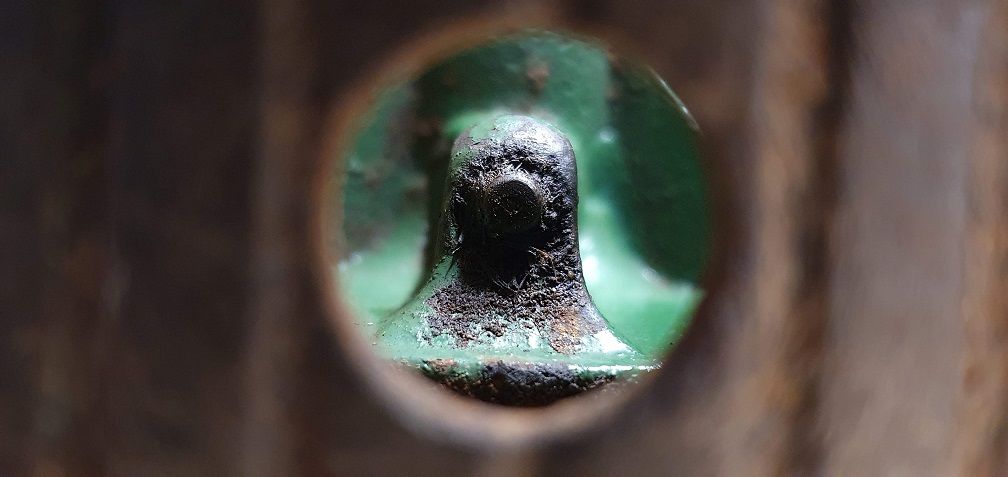
Given the fact the sprocket can turn while the roller halves are held stationary, how does one go about removing the sprocket in order to remove the roller form the chassis? I have read that you can place objects in the oiler holes of the roller halves which will resist the turning of the sprocket when they meet the ground/workbench - is the sprocket left hand thread? - but this isn't the case as my sprocket still turns. On the other end of the roller appears to be a lubrication nipple, behind a (missing) rubber grommet
The bearing caps on the
The bearing caps on the cylinder bearing housings just knock off.
The rear roller halves should free wheel forward when the sprocket is held, but the sprocket should try to turn if the roller half is turned backward. There are three pawls in each roller half, but they have been known to break.
As to removing the sprocket, you appear to have an early version, later versions had a larger shaft with a slot at the non drive end, there was a tool that bolted on using the three bolt holes with a 'tongue' that went into the slot in the end of the shaft and it was still extremely hard to unscrew the sprocket (which if remember correctly, is left hand thread).
you will need to do something similar, hold the rear roller shaft with something (pair of stilsons ?) whilst you attempt to remove the spocket. Once you get the sprocket off (or is that 'if ?), you just remove the three bolts at each end and the roller should drop out.
I think that you will find
I think that you will find that if you unscrew the lubricator ( nipple) that is recessed into the non drive end of the roller shaft it will reveal a slot. I’ve made my own version of the tool that Hortimech remembers and I’m sure that I’ve posted images on this site. The sprocket is left hand thread.
I also did a little article in Grassbox, Ransomes Roller Rescue, showing my method and holding tools for dealing with a totally seizedroller.
The roller sections being stiff and eventually seized to the shaft is the result of greasing rather than the recommended oiling . The grease goes solid in the nipple and the short passage through the roller boss to the shaft. When the shaft is removed and the correct oil gun applied to the nipple and given a smack a solid worm of dry grease will be ejected Into the inside of the shaft boss.
The last sprocket removal that I did really fought to the end . I had to put heat onto the sprocket and sash cramps across the chassis to stop the RH chassis side member flexing and the shaft holding tool springing out of engagement.
I will sort out some images later.
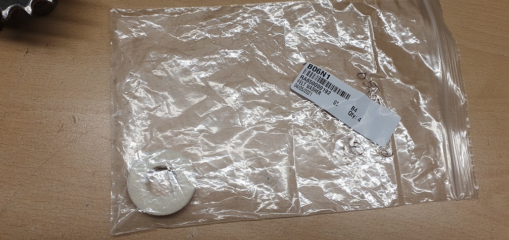
Edit. Meant to say, the felt bearing seals are still available and only £1.50 ish each. The steel discs the keep the felts from getting snagged up in the Bearings are also available at about £4 each. I make my own! Their centre hole has to be big enough for the shoulder of the shaft to pass through it and butt up tight to the bearing inner race without snagging the washer and rotating it. I always soak the felts in oil before fitting them so that they are fully loaded with a good reservoir of oil.
Later!
Thanks for all the
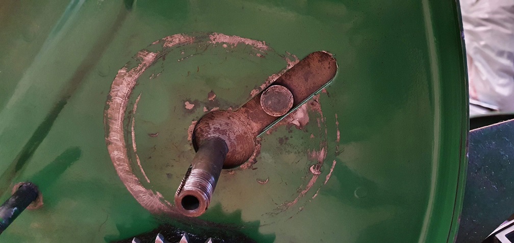
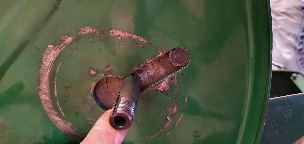
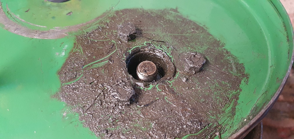
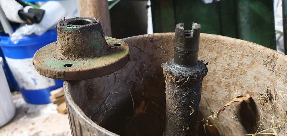
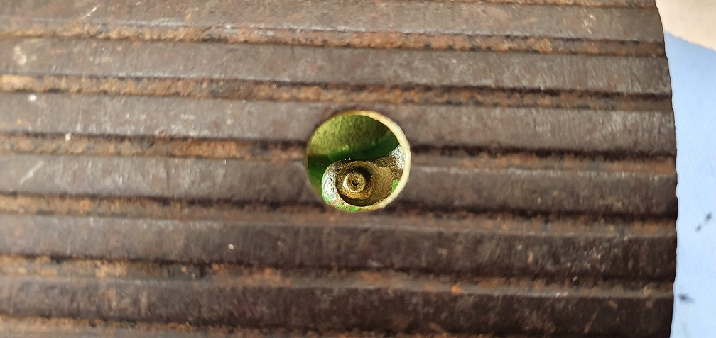
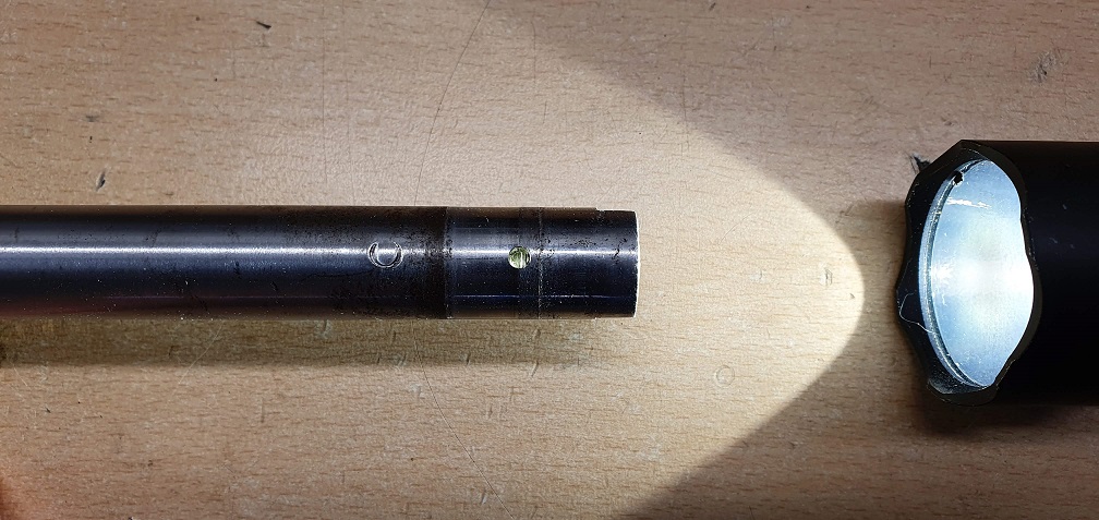
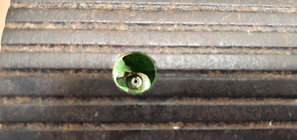
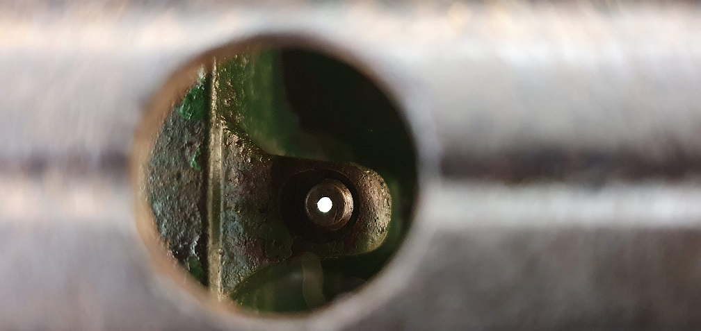
Thanks for all the information and examples/pictures, that's a big help. Apologies, my picture of the lubricator on the non drive end of the shaft was a bit misleading. If I had just dug a bit deeper around the lubricator, I would have uncovered said slot! A lot of hard grease and mud compacted in there - dirt ingress aided by the lack of covering grommet no doubt, so I excavated gently, not quite knowing what to find, but uncovered said slot
My MK4
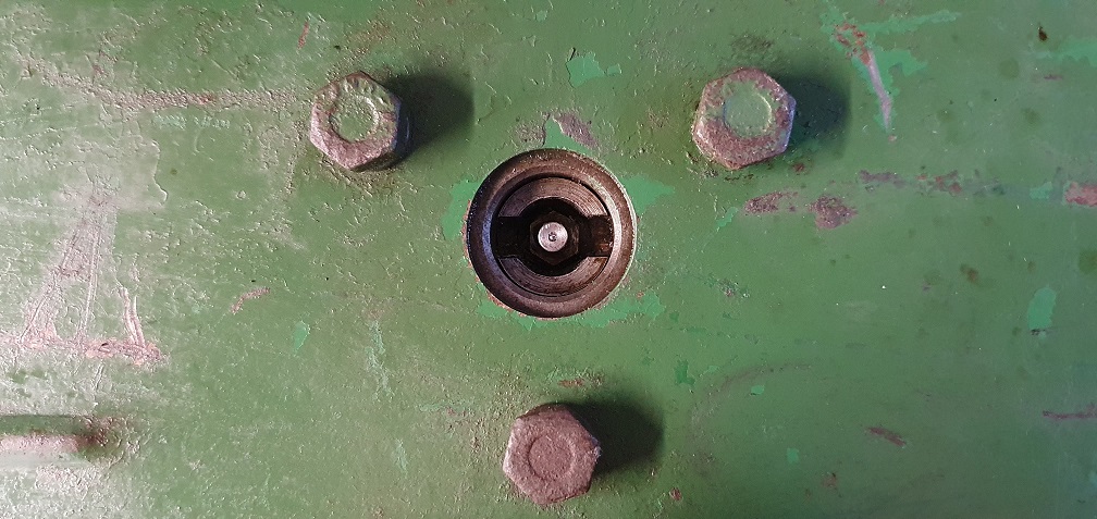
My MK4A (someone has replaced the lubricator with a newer style at some point)
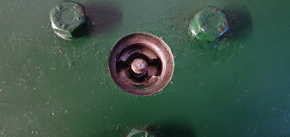
Lubricators removed
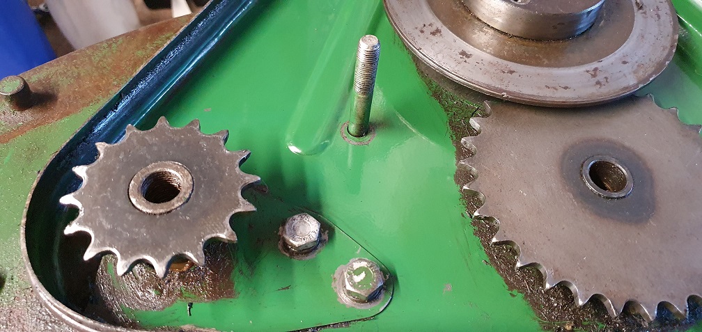
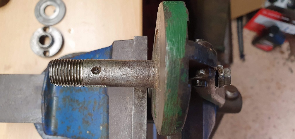
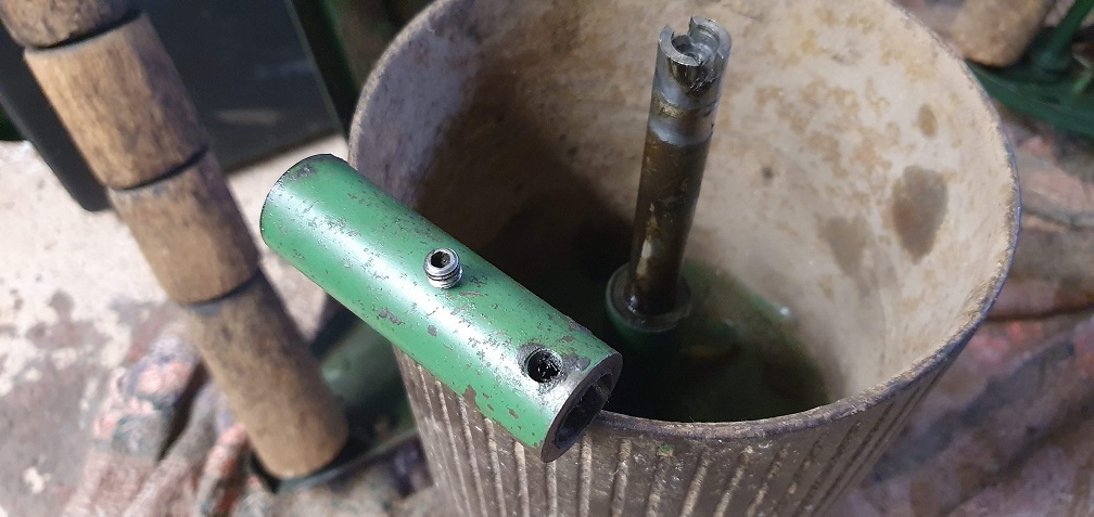
So I can now hopefully prevent the shaft from rotating as I try to remove the sprocket - although it sounds like they normally put up a good fight. I have a length of metal that I can fit a couple of bolts through to sit in between 2 opposing sprocket teeth to hopefully get the leverage I need, but need to find something suitable for the slot at the other end. I have a long 1/2" breaker bar, so If I can find a socket online that has a large thick flat head that fits as tightly as possible into the shaft slot, I can employ a second set of hands on that end to prevent it turning. The slot is quite wide though so a standard flat head socket wouldn't be nearly thick enough. I've seen 'Drag-Link' sockets online before for suspension components, so perhaps something like that. I'll measure up the slot as near as possible.
The tool Hortimech mentions and Angus provides pictures of, which bolts to the side of the chassis makes a lot of sense, but I don't have the means to make anything like that unfortunately.
I have however uncovered (from the depths of an old toolbox I inherited), an Impact Driver which DJD mentioned about in relation to the bottom blade screws
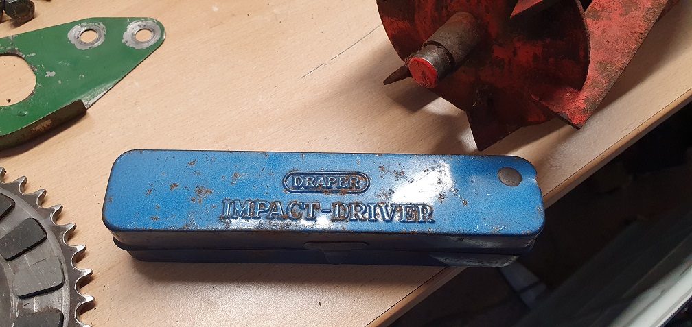
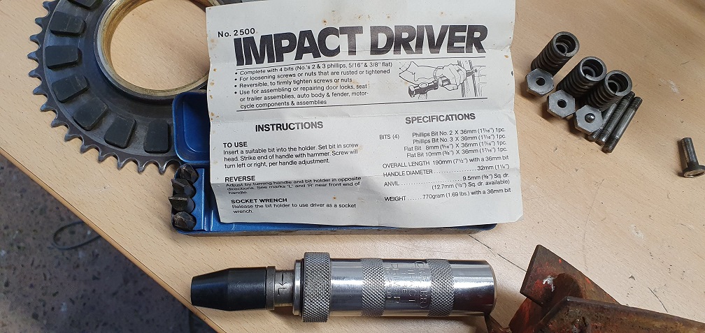
although I'm not sure I will even attempt removal of the screws on any of the blades for fear of making them worse - more soaking in plus gas for a couple of days at least and I'll reconsider
From my experience, impact
From my experience, impact drivers are as much use as a chocolate fire guard when it comes to removing bottom blade screws. I used to use a large centre punch and 'drift' them out, sometimes with the help of heat.
Glad you found the slot, it will help when you come to remove the sprocket, I suggest you find someone to make the holder.
Speak as you find. Depends on
Speak as you find. Depends on the brand of Chocolate! I've had and used one since the 70s - made by a Japanese company, Vessel, and its still going strong . Amazingly the Snap-on man exchanges broken slot head bits under warranty. Interestingly I also have a Snap-on one acquired with a job lot of sockets and wrenches and its not a patch on the Vessel.
Red plastic cover, with
Red plastic cover, with 'Vessel' on the direction adjuster ? I have one of those, it worked for undoing the crosshead screws holding Japanese motorcycle covers on, but it never worked for bottom blade screws, well not for myself.
Red plastic cover, with
Red plastic cover, with 'Vessel' on the direction adjuster ? I have one of those, it worked for undoing the crosshead screws holding Japanese motorcycle covers on, but it never worked for bottom blade screws, well not for myself.
The plot thickens ! The crosshead screws used on Japanese motor cycles, small engines and also possibly on cars conform to JIS standards; Japanese Industrial System which is fractionally different from both Philips or Pozidrive; possibly why we see so many chewed up screws on such equipment . A while ago I decided to obtain some JIS screwdrivers and tracked some down via Amazon; and who was the manufacturer - Vessel.
You can still get a Dremmel
You can still get a Dremmel type mini grinding tool into those screw slots and make them a bit deeper, so that the 'driver bit has something to anchor onto.
Maybe I've been very lucky with bottom blade countersunk screws, haven't come across one I didn't remove yet, not meaning to sound big headed! Mig welding a big nut on and using an air driven impact wrench too will work, someone mentioned a good big centre punch, heat and soaking in diesel etc. that's what we did before impact wrenches and impact drivers were invented!
Some folk on YouTube and so forth are now using acetylene torches to get parts red hot then quenching in cold water, the temperature shocks help a lot, but are not advisable on some jobs.
Very good luck with your projects, wish I could be there to help!
A second pair of much more
A second pair of much more experienced hands would always be welcome - if you happen to be visiting East Devon any time!
I can see about using the Dremmel on the slots of the worst screws, however I still get the feeling that they will require proper heat and welding which I don't have the tools or knowledge for. I've cleaned up the 3 bottom blades around the screws to get a better view of the exact screw condition and likelihood of my own removal - while still soaking in plus gas very so often
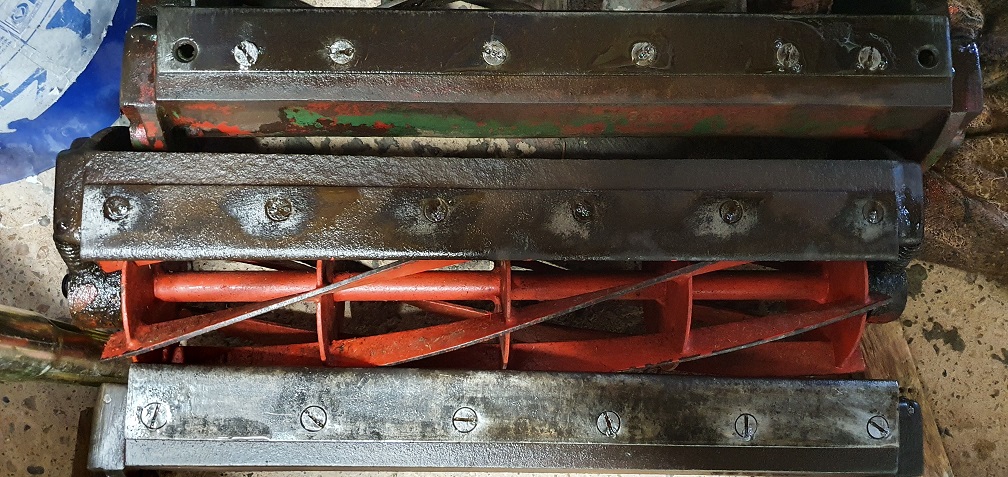
The blade at the bottom of that picture is on my spare cutting unit, and has screws that are fairly unmolested without too much corrosion, so I may stand a chance of getting them removed at least.
Although the incorrect blade at the top, on my current MK4 cutting unit, has clearly been fitted at some point in the not too distant past, going on the condition of the screw material at least, so If i can tidy the slots up I 'might' be able to remove those.
As for the middle blade, the screws look the oldest and most mutilated, so I think that's going to be a weld removal job.
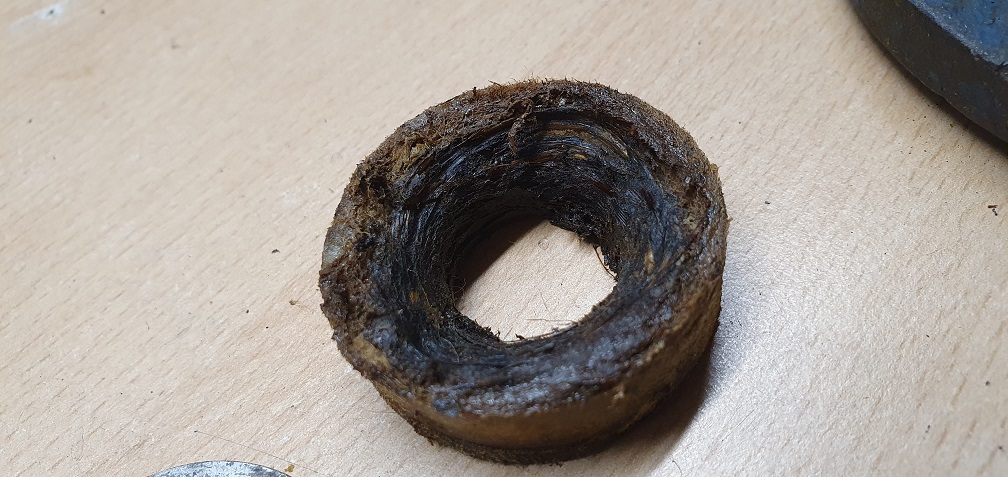
The bearing carriers that I have removed from the spare unit took some work to free the dust caps due to corrosion
and the felts looks more like mini bird nests
Removal of the RL5 bearing from the drive side carrier is easy due to the access hole in the back of the carrier for the cylinder threaded shaft to go through, so I could pull that one out using my makeshift crankshaft bush puller :)
As for the non-drive side bearing carrier, the back is closed, so I can see why people suggest drilling some holes in the back, in order to tap the bearing out
Showing the outer cust cap, felt washer, thin metal washer, RL5 bearing and carrier.
Good opportunity to unblock the lubricators and remove old grease, ready to apply new oil to the new felts and new bearings.
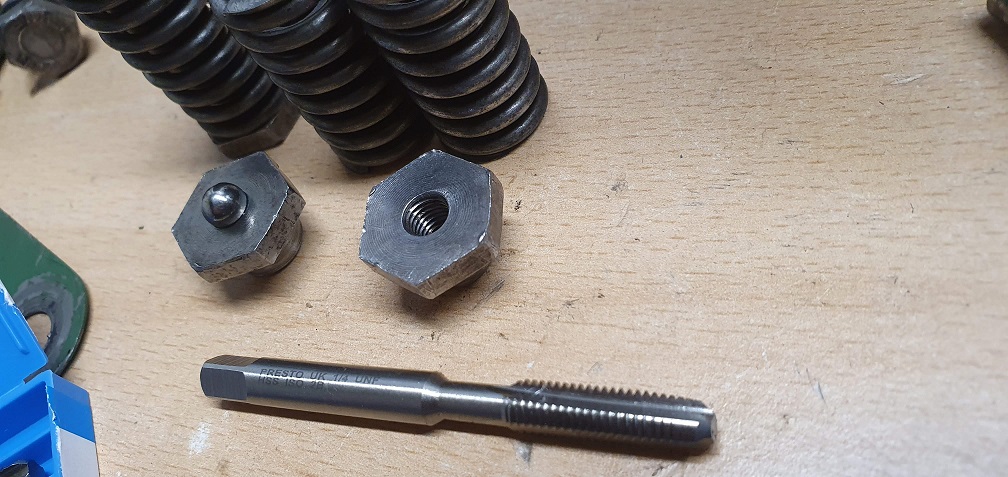
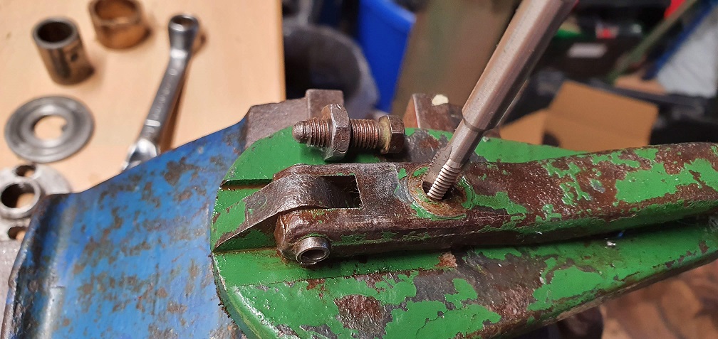
In other news, my replacement studs arrived for the clutch springs
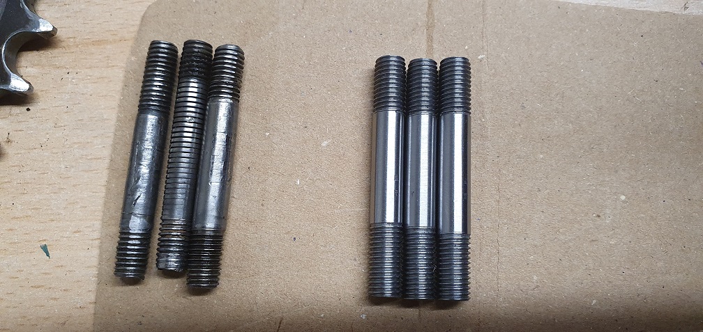
I ran a 1/4" UNF tap through the fixing nuts as they were very tight on the previously damaged threads, and that cleaned then up a treat. Careful to only use finger pressure slowly to pick up the existing threads and just clean them through. Now the nuts screw on nice and smooth on the the studs. I'll do the same on the clutch threads that these studs screw into also
Ah, JIS! I have a set of mini
Ah, JIS! I have a set of mini-JIS screwdrivers, I think I bought them when I went through a period of repairing Olympus Trip35 cameras, before they were cool again and you could still pick them up for under a fiver. They don't look different until you look very closely, but the difference having the right shaped head makes is inestimable!
I still have quite a few new
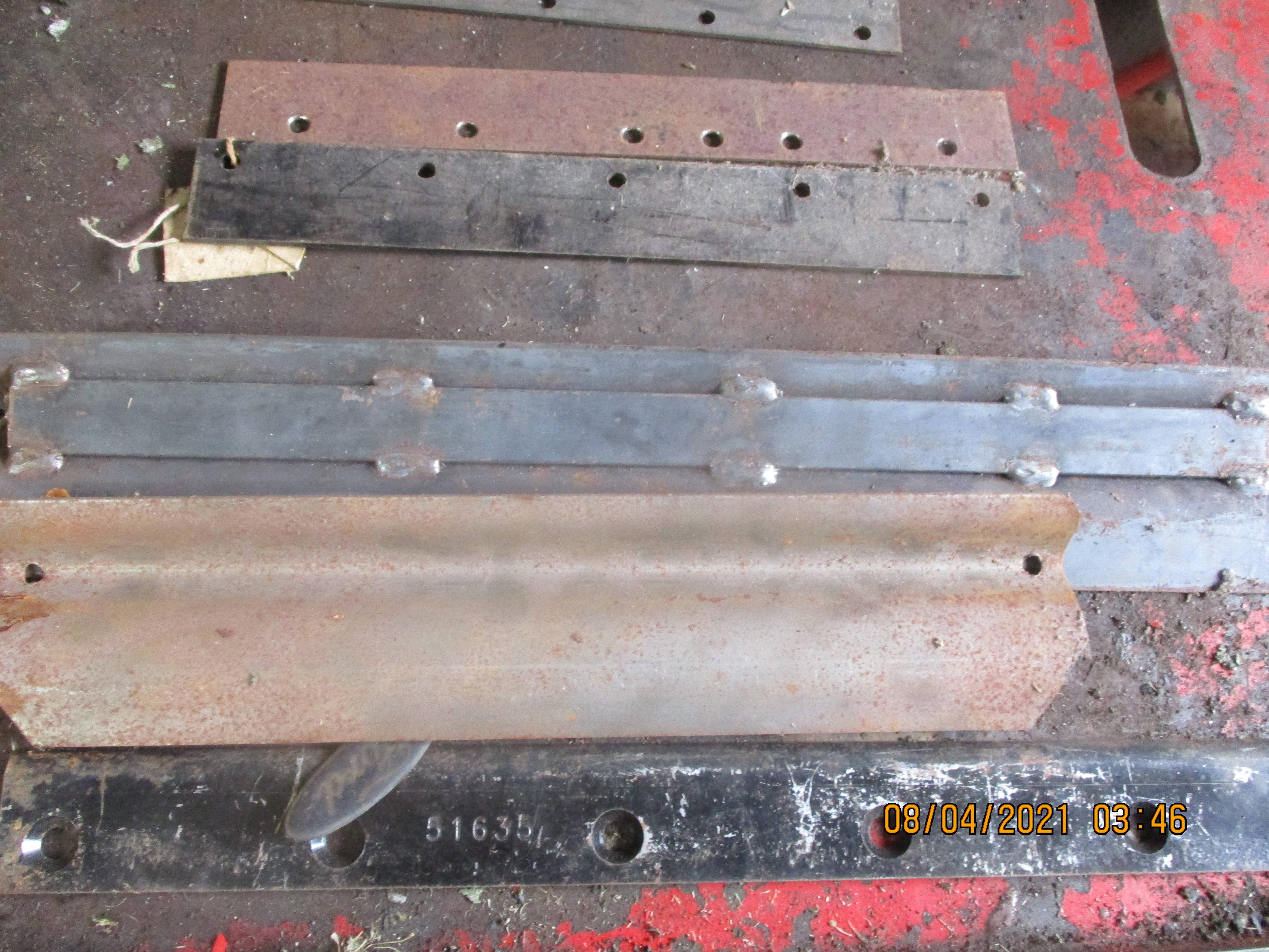 I still have quite a few new bottom blades knocking about, I'm not sure if these are Atco or Ransomes, I can't even remember buying them now.
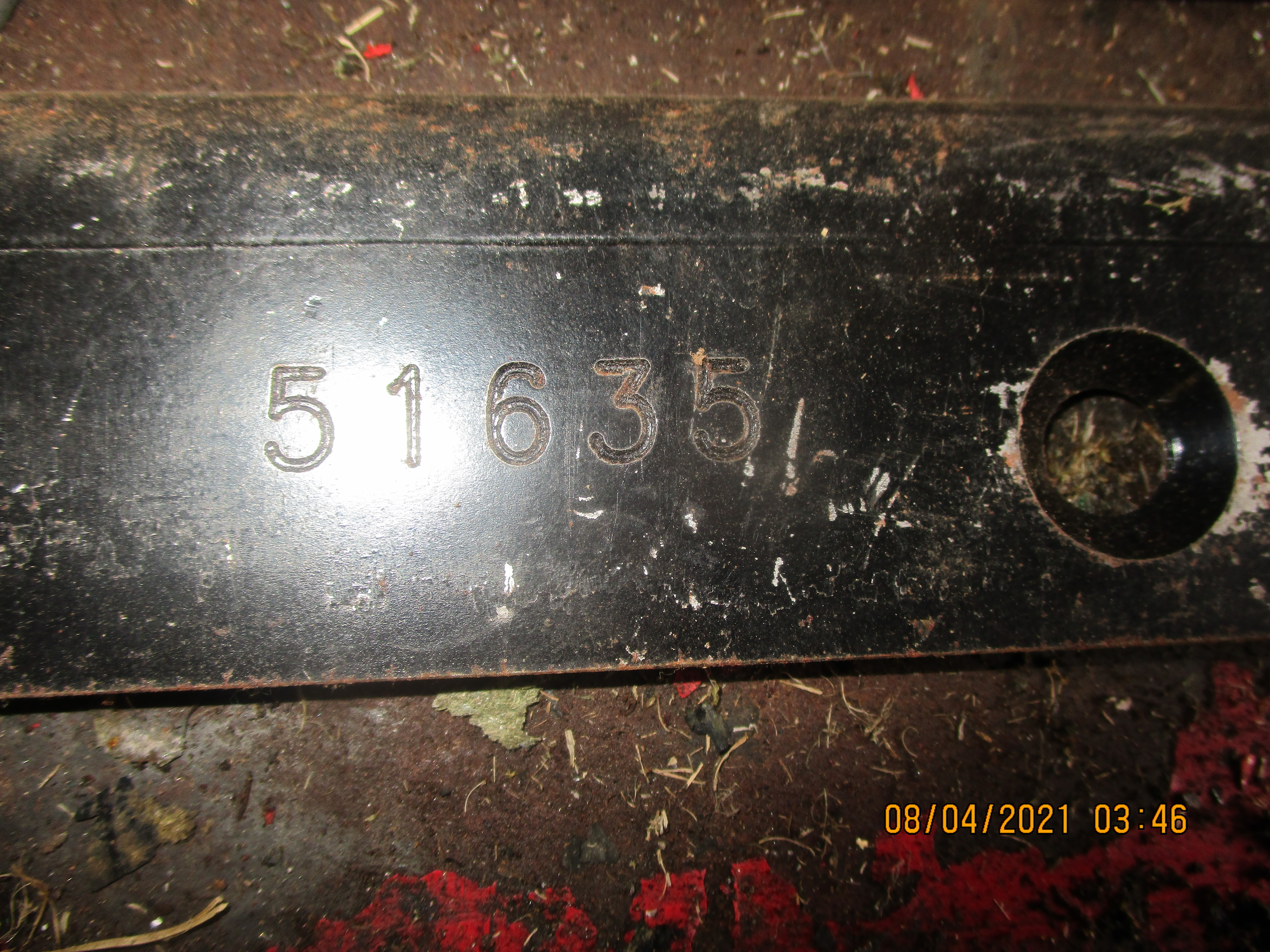 Maybe this number may help, others may recognise it if a genuine Atco/Ransomes part number?
The 51635 blade looks like a
The 51635 blade looks like a Central Spares part number for a Ransomes - possibly Marquis, equivalent to the Ransomes part MBA7016 assuming the 6th hole is out of shot in the top picture, and that it has a lipped blade? I'm not sure the Ford badge would have come with it though :)
The one above that looks like the same one used on my Atco/Suffolk Super Colt and other similar machines.
A small victory to report - I
A small victory to report - I removed the first of the 3 bottom blades myself without any heat, after days of soaking the screws from either side with plug gas - and the newly discovered impact driver. Admittedly it was the easiest of the 3 blades, given the good condition of the screws and lack of rust around the heads, but I felt brave trying at least one screw as long as I was careful and stopped at the first sign of making things worse. Lesson learnt from my stud removal attempt.....
The blade on the spare cutting unit was my target

The blade itself, to my amateur eyes, looks to be in good condition with minimal wear, comparing it against the profile of a new blade, so a skim should make this a perfectly usable blade - giving me my first full set of cylinder, sole plate and bottom blade for cleaning up and sharpening
The non drive side RL5 cylinder bearing looks to be the original given the state of it - definitely in need of replacement
so time to mark out 2 or 3 spots to drill holes through the back in order to tap it out as I can't see any other way of removing the outer race.
It looks like someone has done this in the past on one of the other bearing carriers - although it appears the initial hole was maybe drilled in teh wrong place!
and these appear to have been filled again with maybe solder or something. What is the usual practice here - once the new bearing is fitted, fill the holes with maybe silicone or something to prevent dirt ingress but allow for future ease of removal - should the machine see enough years to warrant a further replacement!?
so time to mark out 2 or 3
so time to mark out 2 or 3 spots to drill holes through the back in order to tap it out as I can't see any other way of removing the outer race.
Get your measurements correct and it only needs two holes. Only drill a hole less than the width of the outer race and the new bearing will cover it when installed, so sealing it is not really an issue, a bit of heavy grease is adequate. There is another way, if you have a welder. Run a bead round in side the outer race, let it cool and it will shrink enough that it will fall out.
That sounds like a very
That sounds like a very useful trick with the welder. Sadly no welding equipment or skills - maybe one day I'll take a course. It seems to open up all sorts of possibilities if you have the skill and equipment to weld, from making up required 'tools' to the removal of stubborn parts.
I found measuring and marking out the holes to drill in the back of the bearing carrier quite difficult. Trying to take a reference point to measure to the centre when most of the outside has a taper to it. A lot of looks and judging by eye mixed with as accurate a measurement as I could take, plus a bit of luck, it worked out spot on! Drilled through until I could feel the bearing material and then punched the rusty bearing out far enough to get my puller on it and finish the job
So that's the first pair of carriers sorted ready to be rebuilt with new bearings and felts. Feels like I'm gaining some momentum at last...
As I would be replacing the
As I would be replacing the bearing anyway, on the second set of bearing carriers, I tried using my bearing extractor and successfully removed the bearing from the non-drive side carrier without the need to drill holes - and get lucky with the positioning a second time!
It took a few hits of the sliding hammer but cane out fine leaving the carrier in tact. Carriers cleaned up and new RL5 bearings pressed in to all 4 carriers
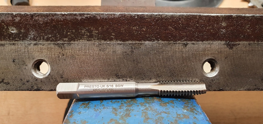
Ran the tap through the lubricator hole threads in the carriers to clear them, and also ran the BSW tap through the first sole plate screw threads to clean them up
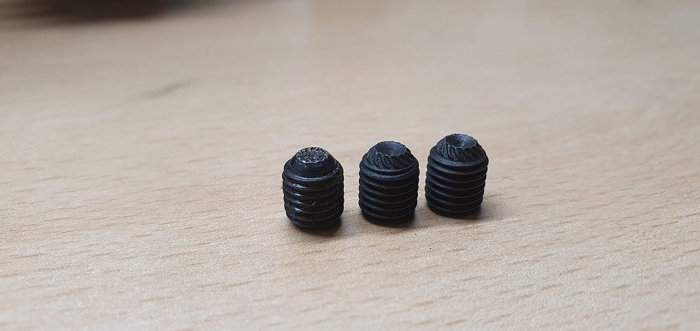
Due to one missing clutch drum securing grub screw, I ordered a pack of 1/4" x 5/16" knurled cup head replacements so will fit 2 new ones to ensure a good bite into the key surface (old screw on the left below)
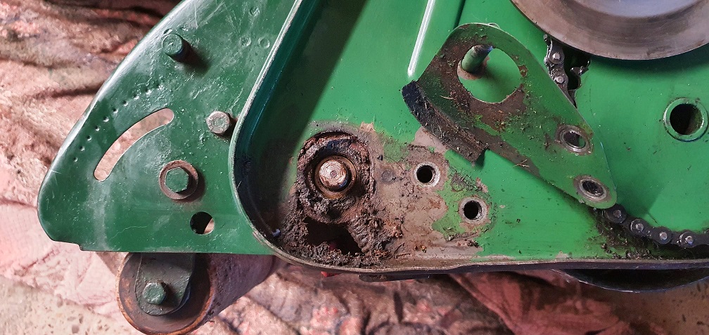
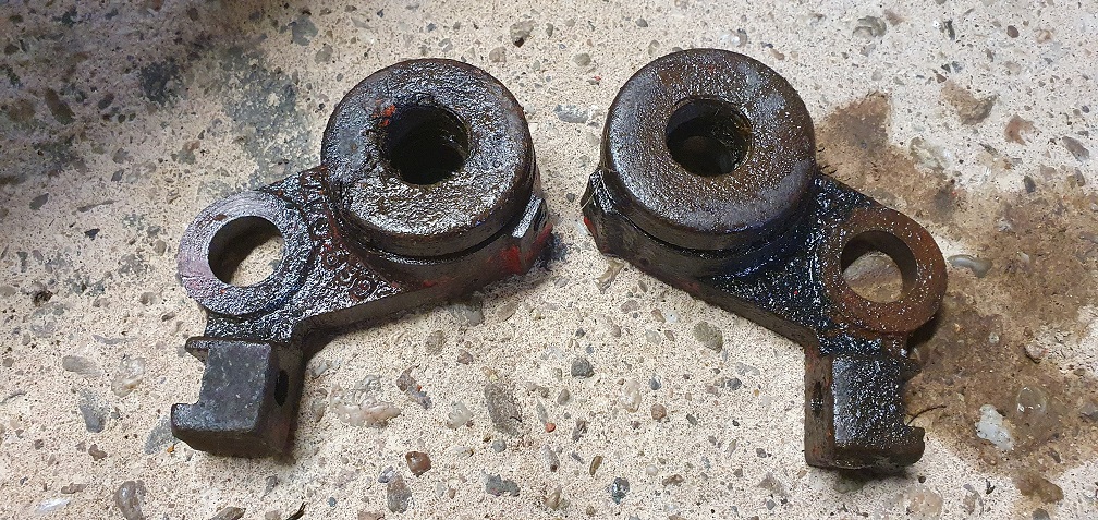
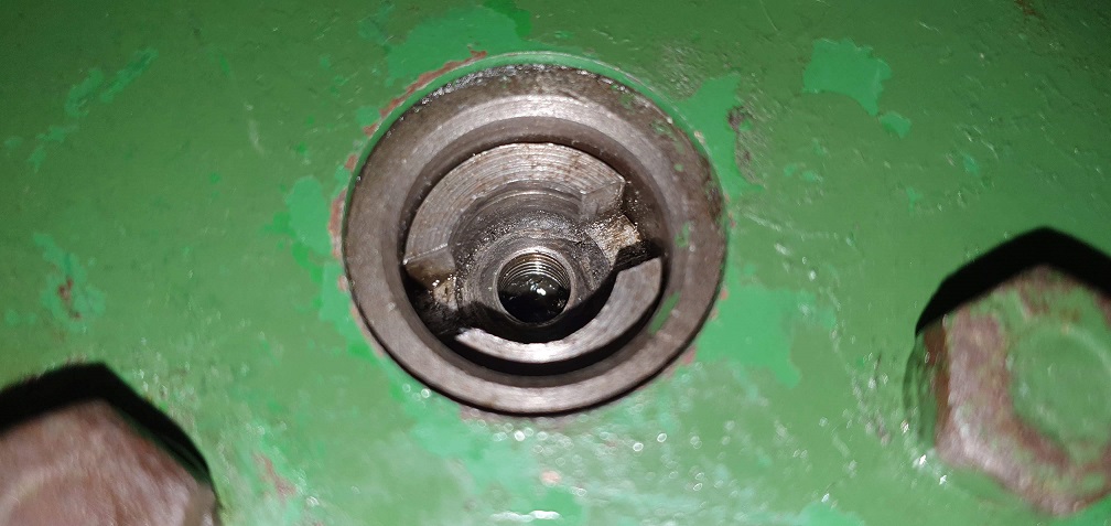
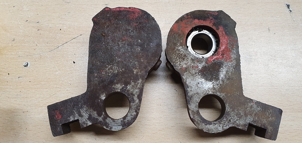
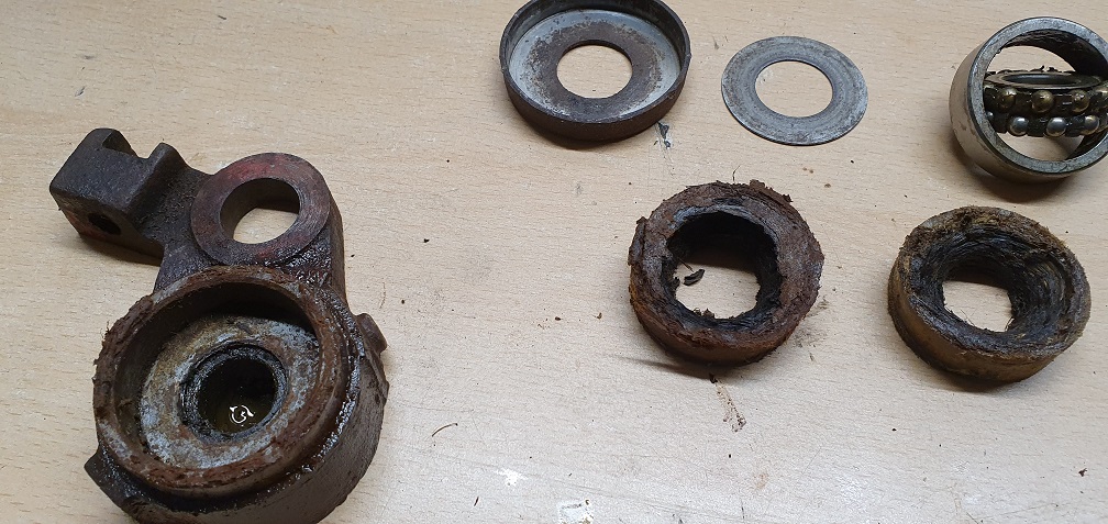
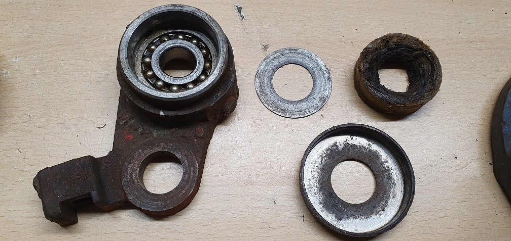
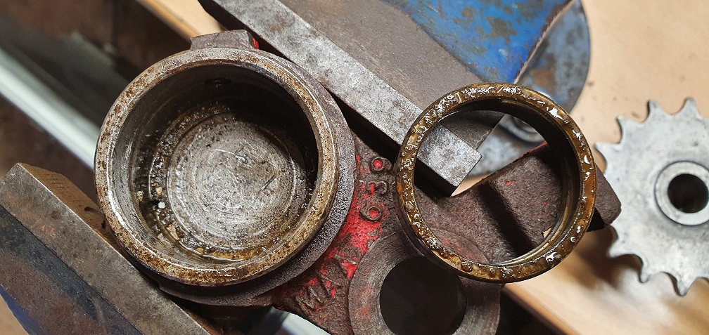
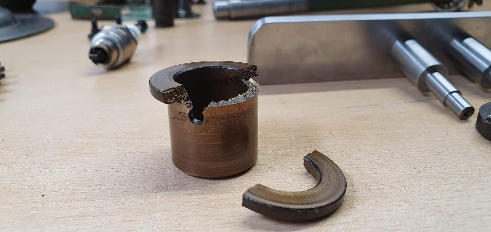
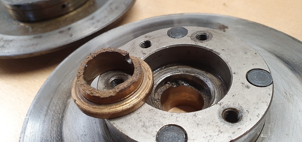
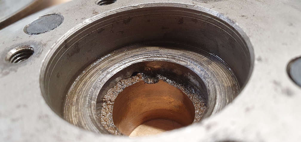
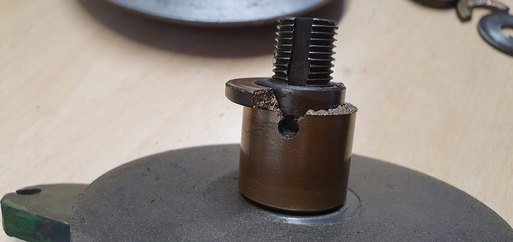
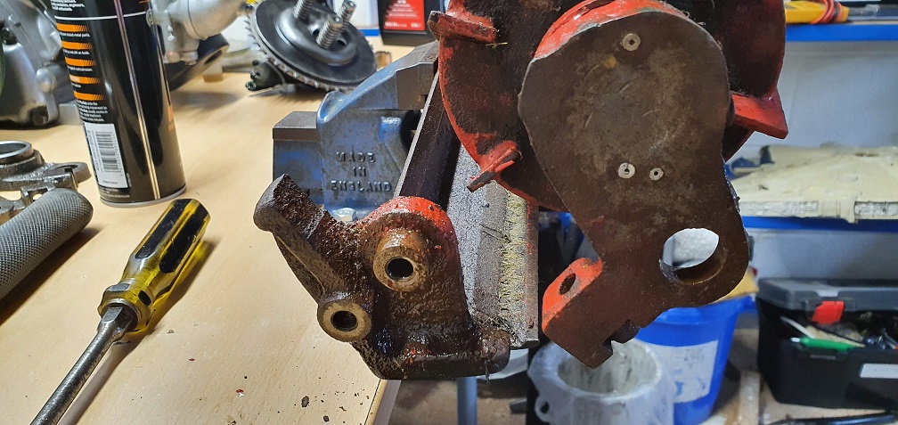
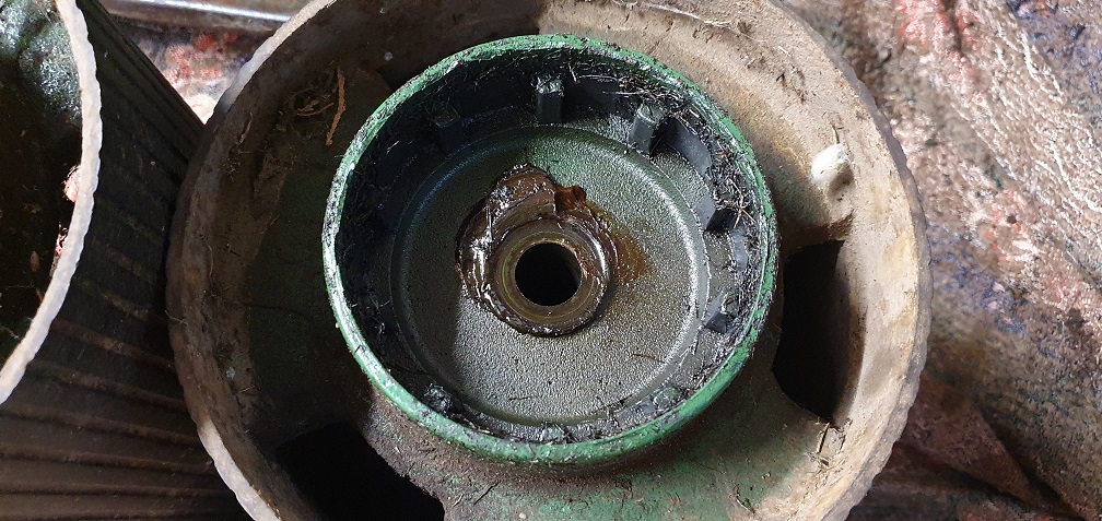
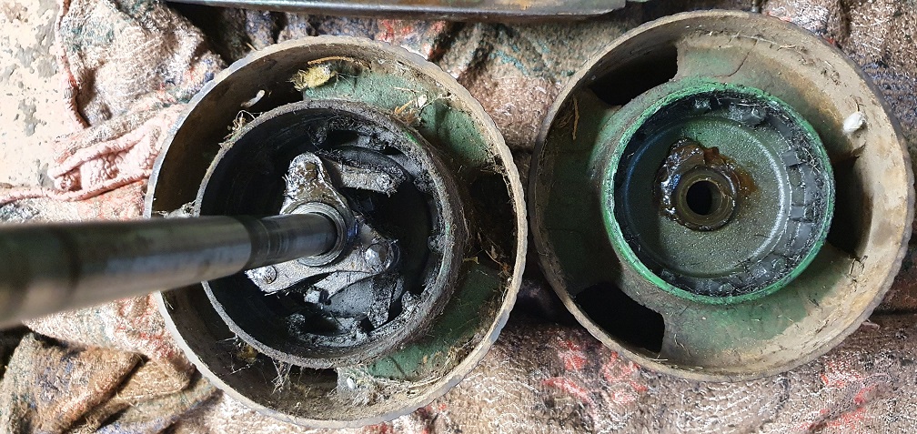
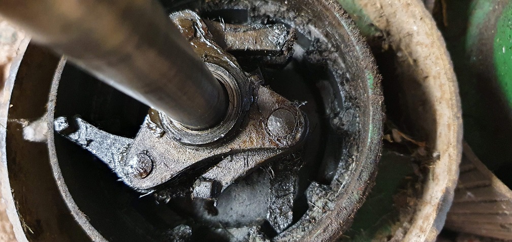
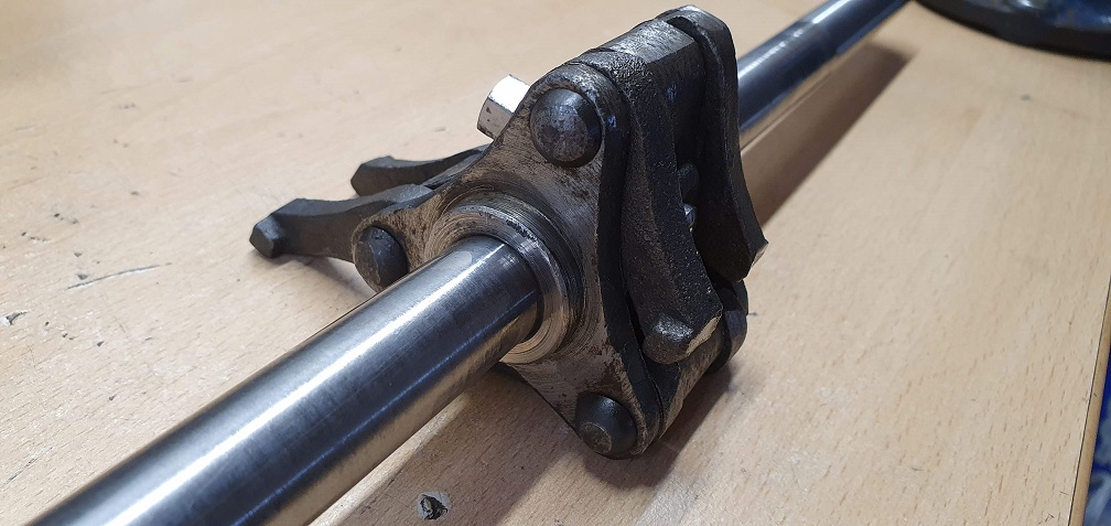
In other slightly disheartening news, I finally removed the clutch retaining nut on both mowers. The nut on the MK4 came off ok but the nut on the MK4A has been overtightened in the past so took considerable effort and leverage to get undone. The overtightening may be a coincidence or could be due to what was underneath. Having read a post on here from Wristpin on Chris G's Marquis restoration thread some time ago, I was aware that the bronze top hat bush behind this nut has been known to fracture, so not surprised, but very disappointed, I discovered BOTH of my mowers have a broken top hat bush :( I seem to have all the luck
MK4
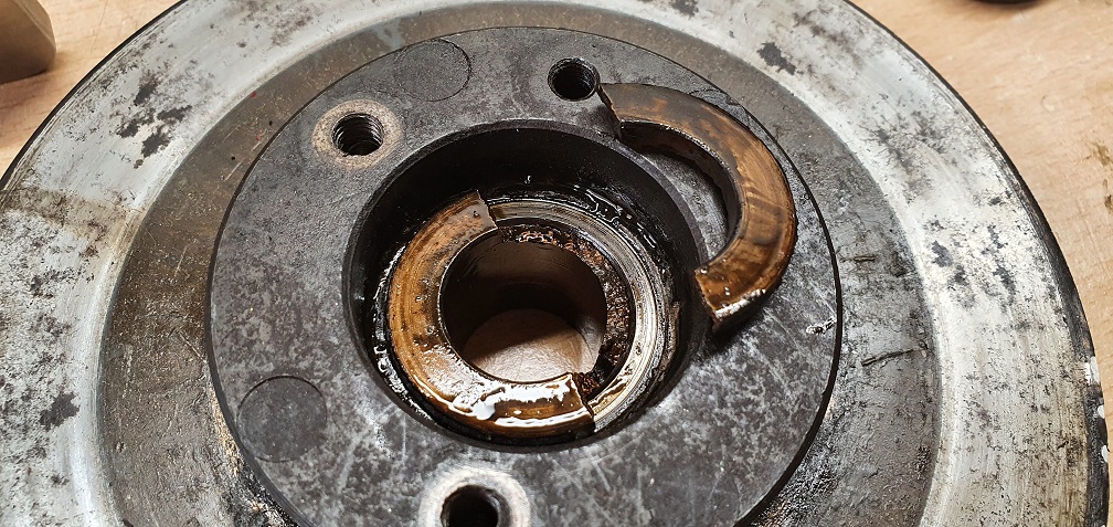
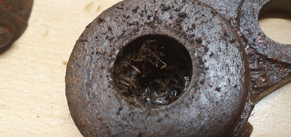
This could have seized at some point due to lack of lubrication, as the steel bush that runs inside this top hat bush has been fitted the wrong way around, meaning that the oil feed from the lubricator would have been unable to lien up with and deliver oil to the oil passage
Incorrect fitment
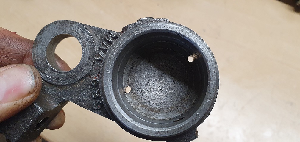
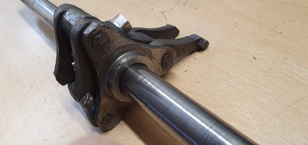
On my MK4A this steel bush was fitted the correct way around - with the oil hole nearest the outer end of the spindle
Although this was correct, the oil hole from the lubricator to the top hat bush was jammed with old grease, so on the MK4A this could have led to the seizure perhaps
MK4A
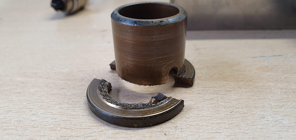
The flange section on this one is intact, but broken around the oil hole line
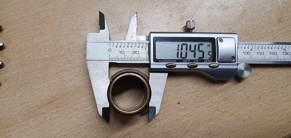
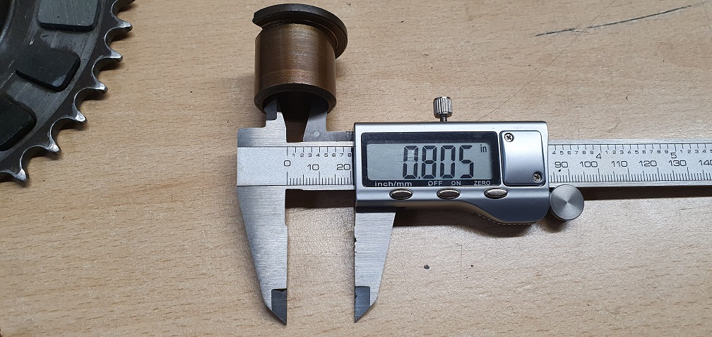
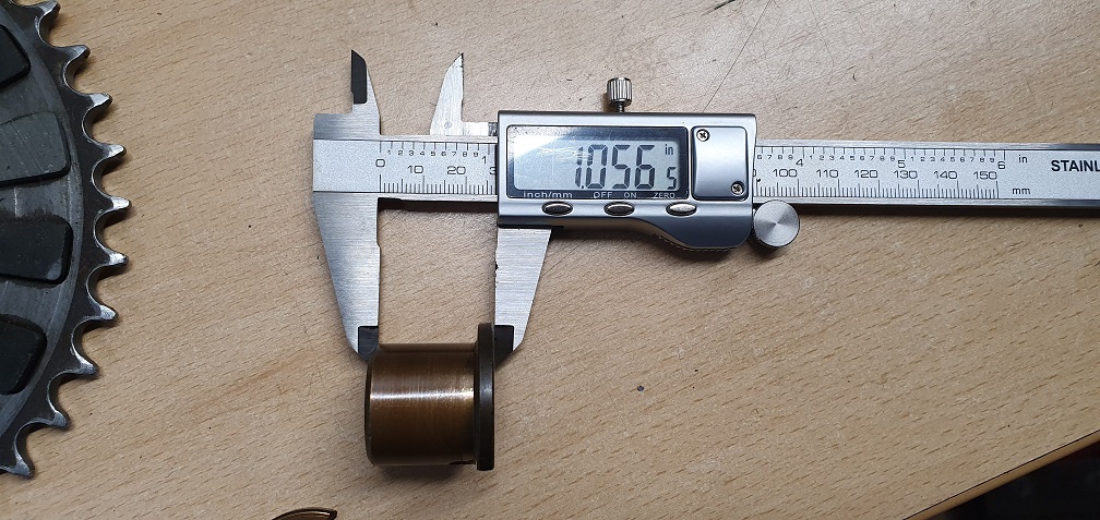
So 2 new top hat / flanged oilite bushings required, as repair doesn't look like an option. Original part number LCG 1458, however I will measure the dimensions and see if any generic replacements of the correct size are available.....
That’s a bit of a B****r .
That’s a bit of a B****r . My endeavours to find an off the peg top hat bush of either th correct dimensions or of dimensions that could be machined down, came to naught. I wish you greater success. On one machine the incorrect inner bush may have contributed to the failure as may have the use of grease rather than oil. However, looking at the images showing the failed parts still in the clutches, it does appear that the oil holes in both are slightly misaligned - another possible contributory factor?
It may be worth trying a no cost option. Press out the bush from the back, putting the pressure evenly distributed on the undamaged surface. Freeze the broken bush and press it back in to line up with the oil passage and when it comes to reassembly time carefully line up the fractured ends and clamp up the clutch boss and roller sprockets before assembling the main sprocket and pressure plate. Oil liberally. I think that you will get away with it , and there is little to loose if you don’t. Interestingly, another manufacturer using a similar design of clutch with a top hat bush , switched to an ordinary tubular oilite bush with a separate heavy washer in place of the flange of the top hat.
Give out the correct
Give out the correct dimensions of the top hat bush, I have quite a collection that might include the one you need.
Thank you both. Angus - your
Thank you both. Angus - your suggestion makes sense and I wonder if a previous owner has done exactly that, in order to avoid replacing the bush. If I have no luck sourcing replacements then at least there is that option. I saw the mower in action before buying so I know the clutch 'works' in it's present state. Interesting that the other manufacturer switched to a separate heavy washer and plain bush...
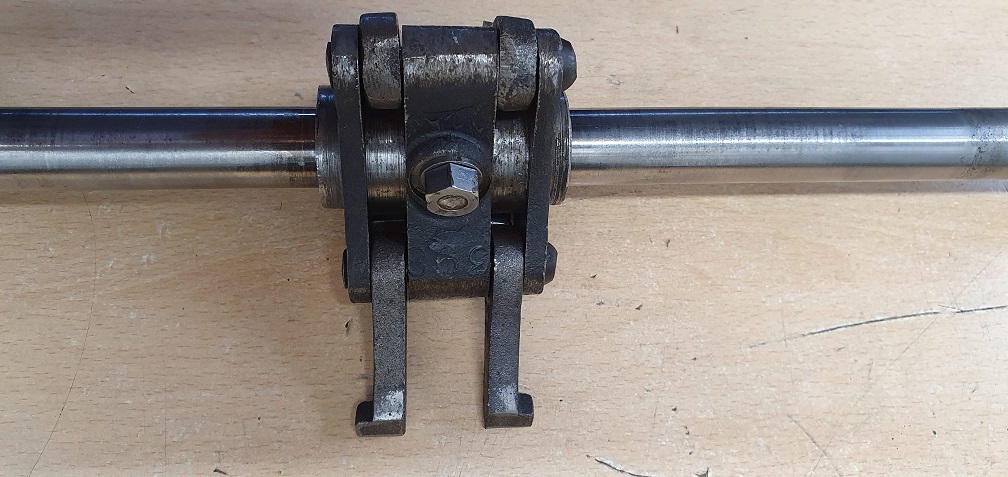
Both bushes were indeed inserted incorrectly - with the oil hole not lined up with the hole in the housing that they press into, and given the grease blocking the oil passage, neither bush stood much chance of surviving like that. Given the keyed washer that sits in front of the top hat bush, I expected to see the inner steel bush also keyed onto the spindle, however that one is free to rotate around on the spindle. Is this to enable the steel bush's oil hole to feed both the intermediate wheel area as well as down into the middle of the spindle where the push rod and ball bearing are?
I've taken some measurements of the bushes, as accurate as I can with my verniers, however the one with half a broken flange simply slid out, and the other bush with the completely broken flange section needed to be pressed out as a much tighter fit. The measurements I've taken are from the first bush which slid out, so probably include a degree of wear compared with the original exact press fit sizes. I will also measure the OD of the inner steel bush that rotates inside this top hat bush, as well as the ID of the housing that the top hat bush presses into as this may lead to more accurate 'required' dimensions
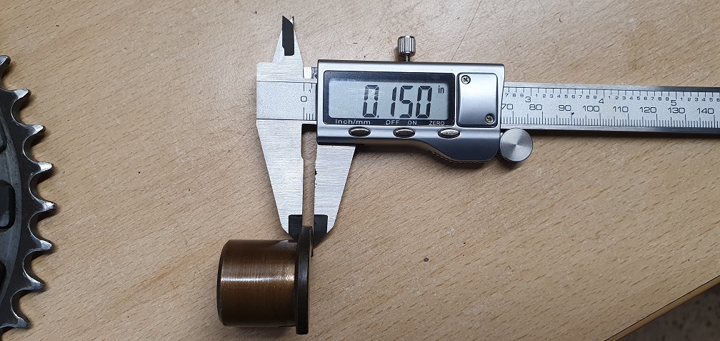
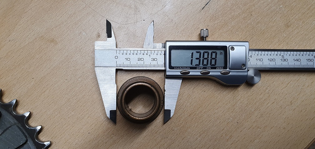
I found thirteen of roughly
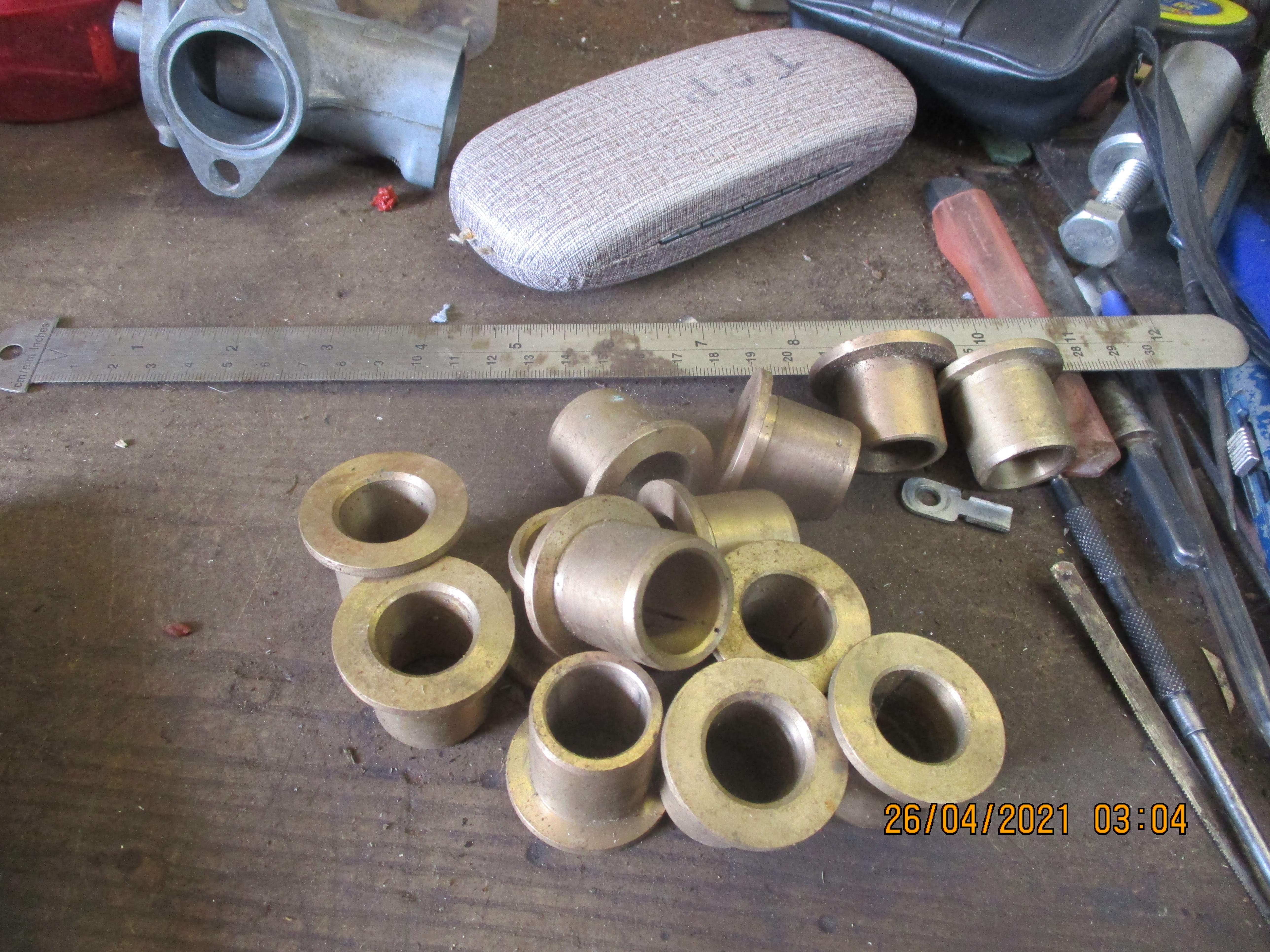 I found thirteen of roughly right size, but none were actually just right, some sizes could have been machined smaller, but alas one of the main requirements, the main outer body size was too small by about 30 thou's.
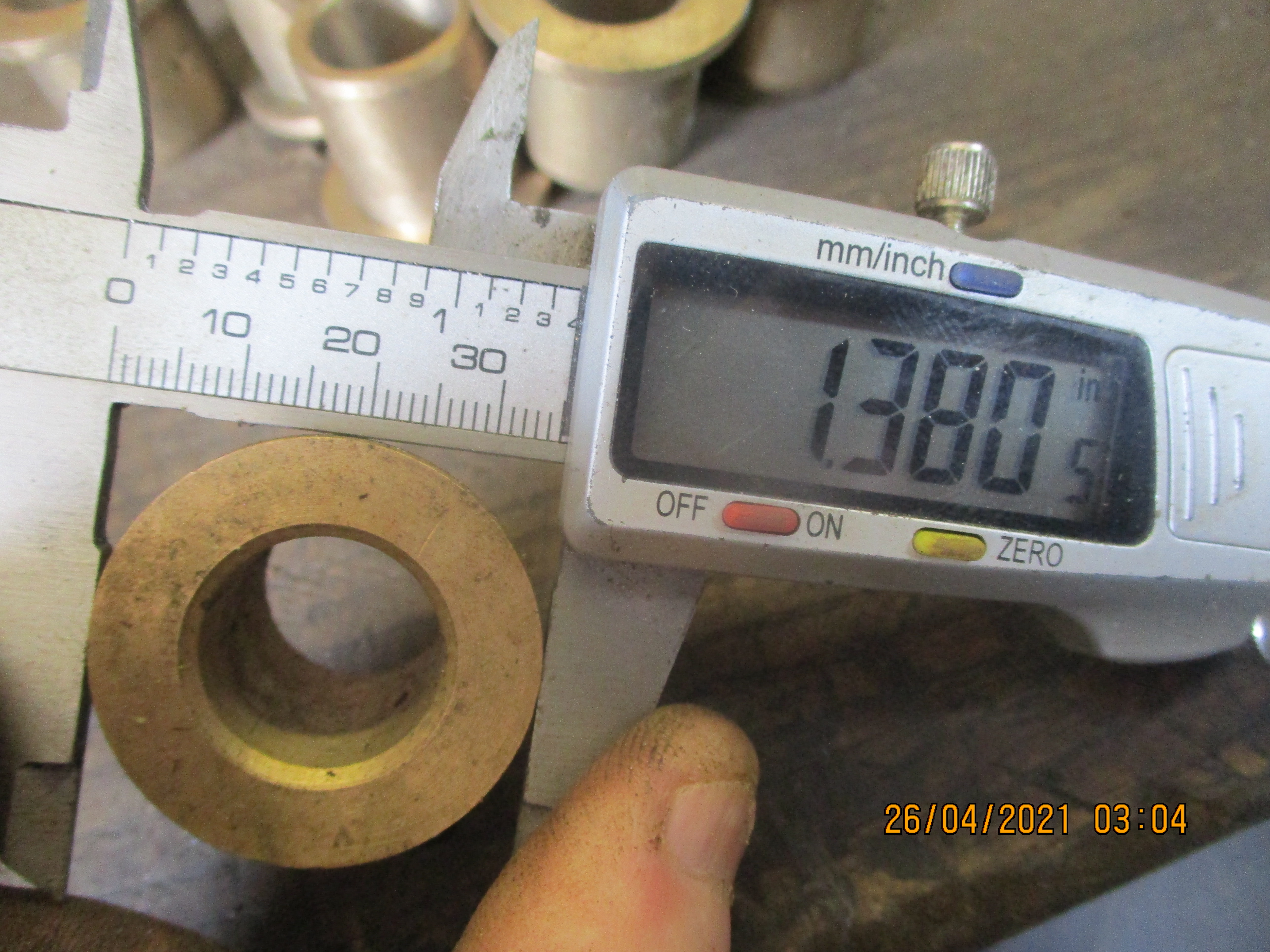
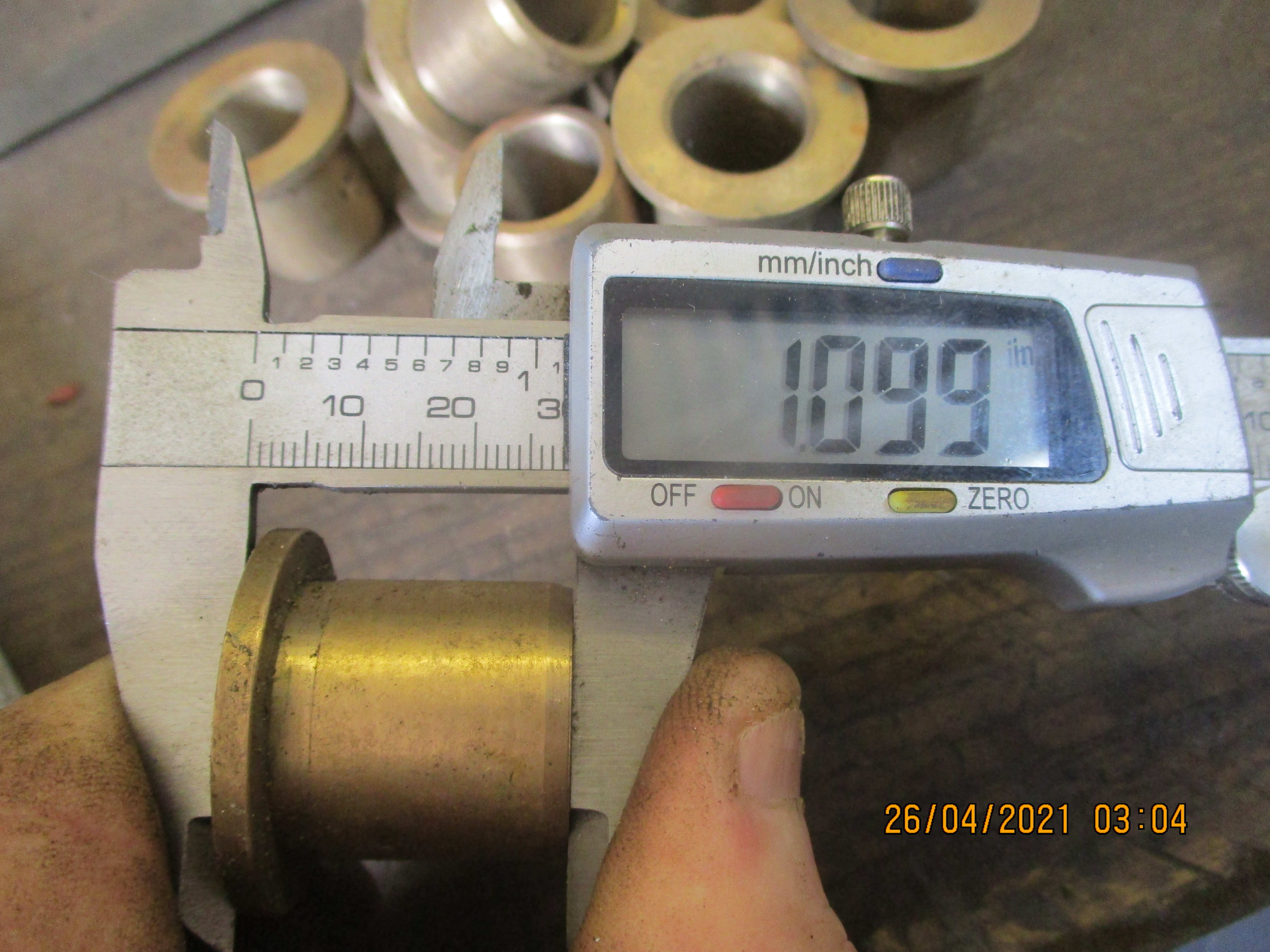
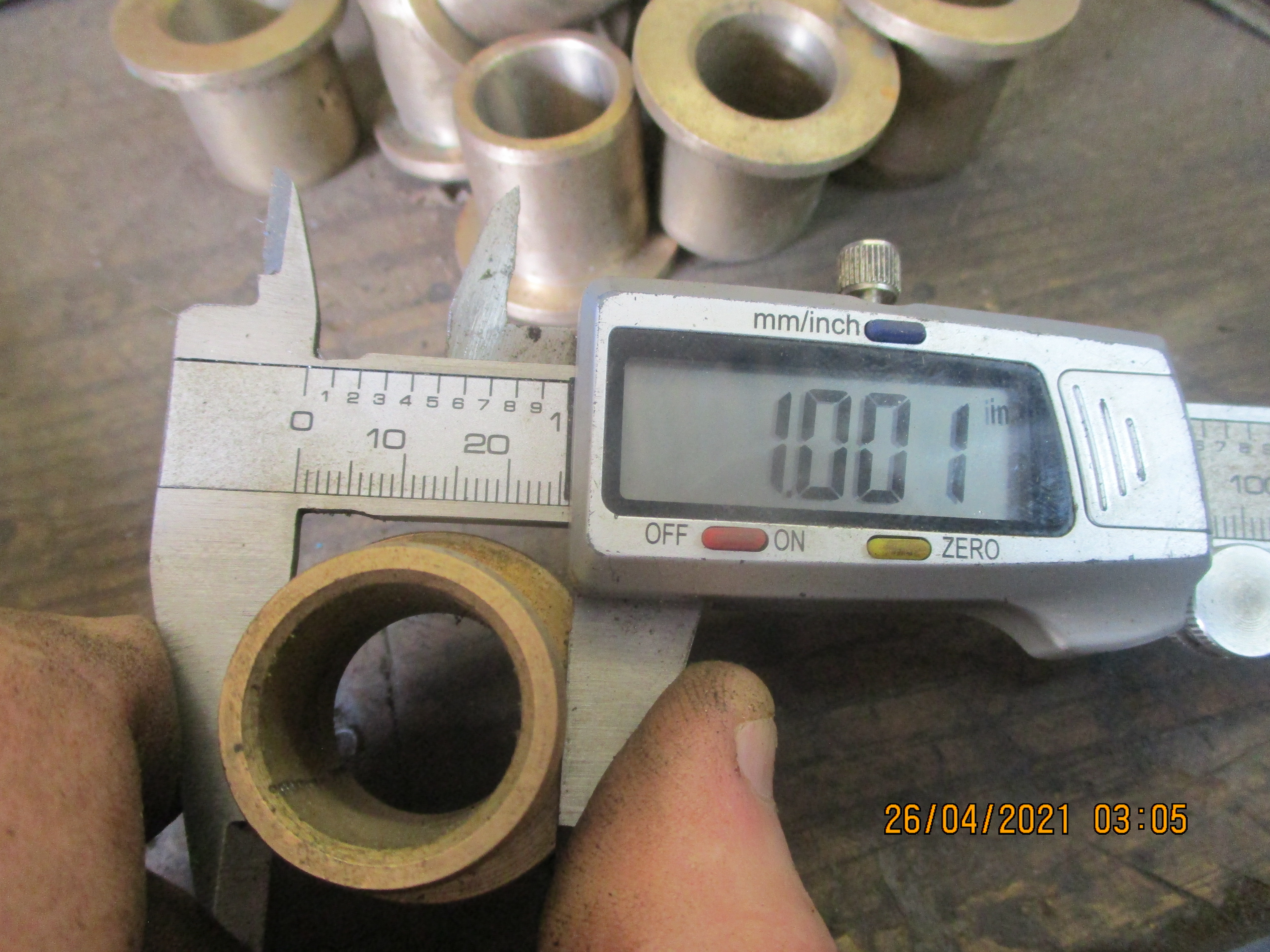 About an inch, rather than the inch and 45 thou's you quoted.
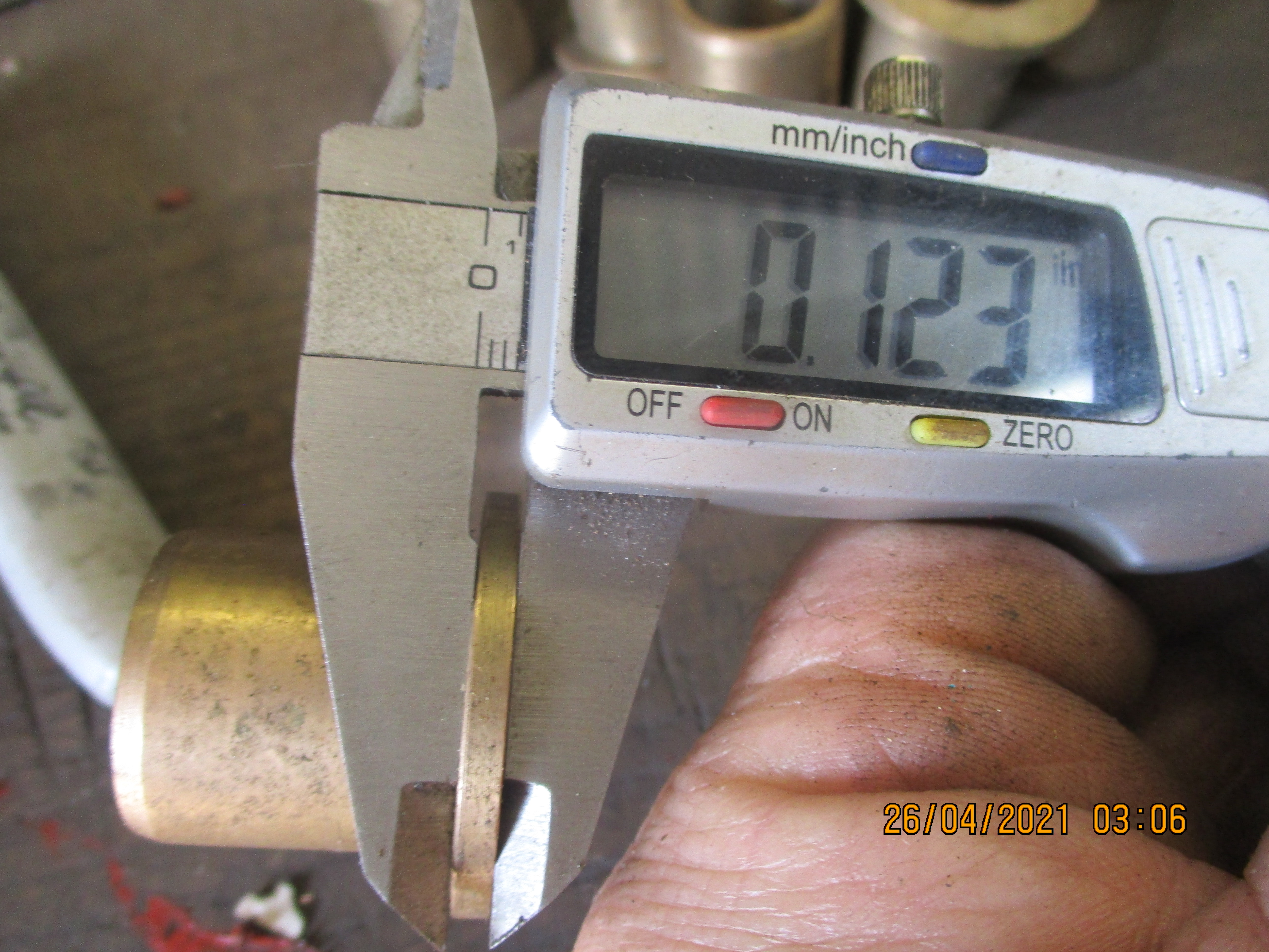 The flange is a tad thin too.
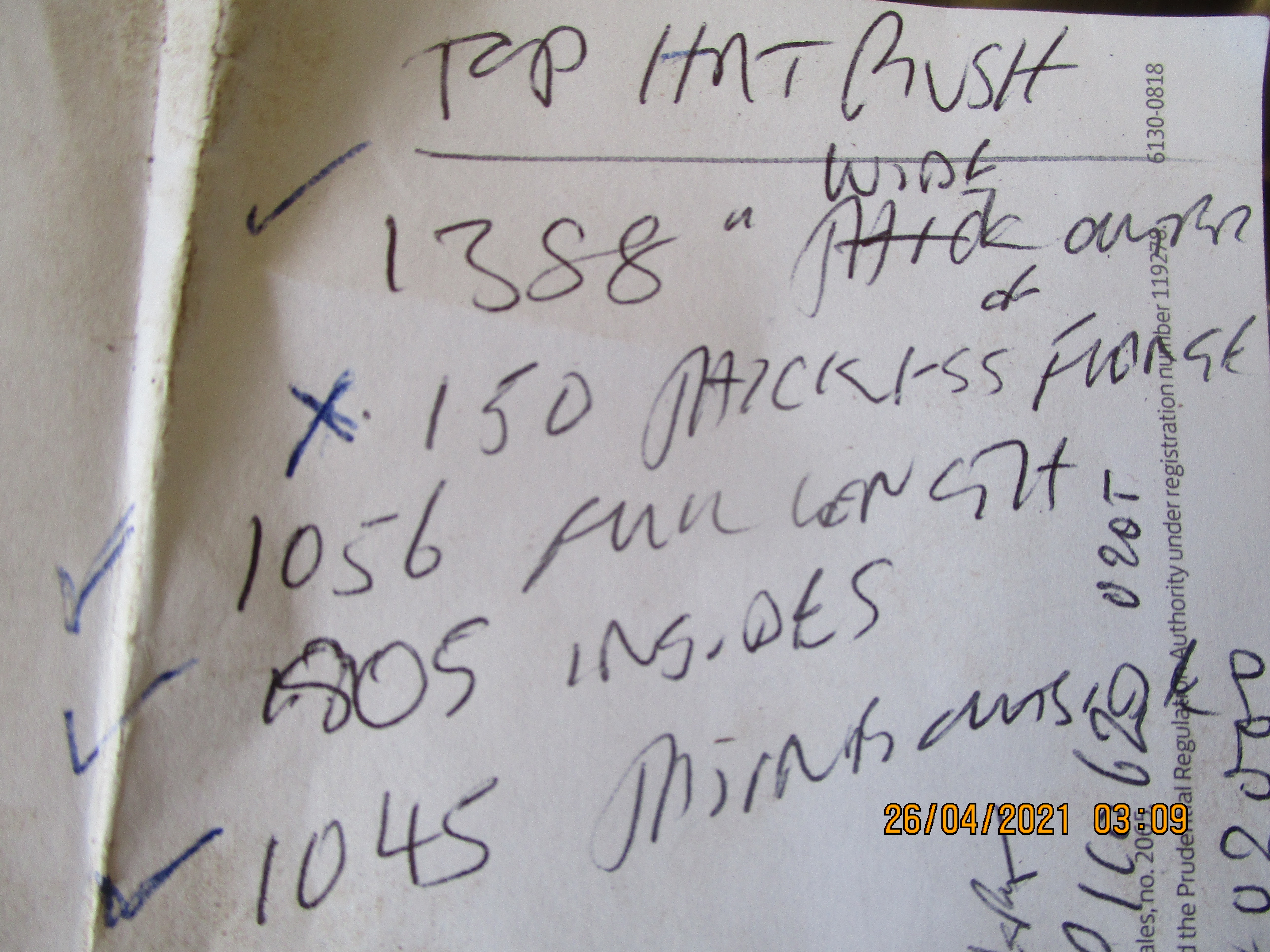 If you can interpret my scrawl you will see that my ready made bushes are not quite up to spec. The bottom tick ought to be a cross also.
Nice collection of top hats
Nice collection of top hats there! Thanks very much for taking the time to look them out and check the sizes - much appreciated and a real shame none are quite right or suitable for machining down. Saying that, even if I can find an oversized item, I don't know how well the sintered material would machine down? I've sent out some email enquiries to some Ransomes dealers and am waiting on replies with availability/cost for the original part number and will go from there. Failing that, I will keep an eye for any local Marquis mowers being broken or sold for repairs, and hope I can find a good condition used item. It would be interesting to get the exact measurements of a new genuine item that has no wear.
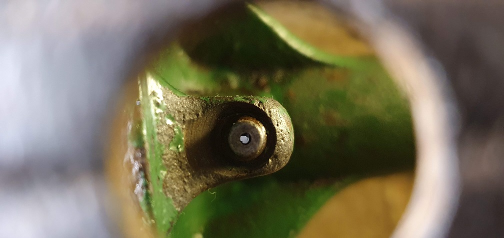
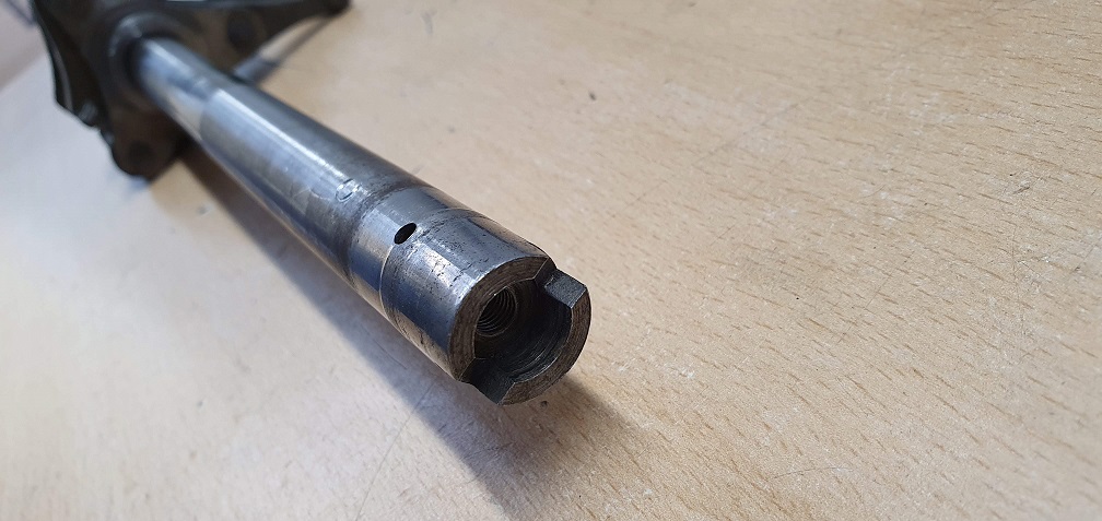
A few more small updates to the build thread in the meantime. The importance of fitting the inner steel bush with the oil hole the correct way around on the clutch spindle
The oil hole in the steel bush needs to be able to take an oil feed from the oil hole in the flanged bush, which itself needs to be lined up when pressed into the hub, to meet the oil hole which is fed from the lubricator. The steel bush oil hole feeds oil in two ways - the first is feeding it into the milled out oilway in the clutch spindle, and the second is feeding it to another oil hole in the spindle, which feeds the spindle internally, for the push rods ball bearing
So while I try to source replacement flanged bushes, the remaining clutch mechanism received a clean up. The MK4 clutch spindle oil feed hole was blocked with solidified grease, and required some work to clear out
The adjusting screw and nut required a little soaking to free up and remove, so cleaned out the hole threads (1/4" UNF) and the threads on the screw to allow easy adjustment when all back together - a tip I saw in Wristpins Marquis Mutterings thread :)
One cleaned up, one more to go!
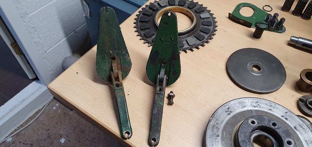
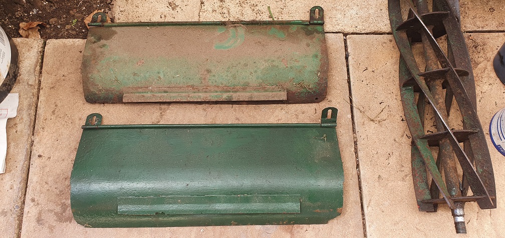
Grass throw plates and hinges all in pretty good condition for age, so will just be cleaned up
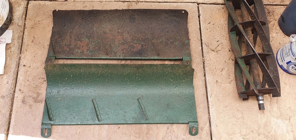
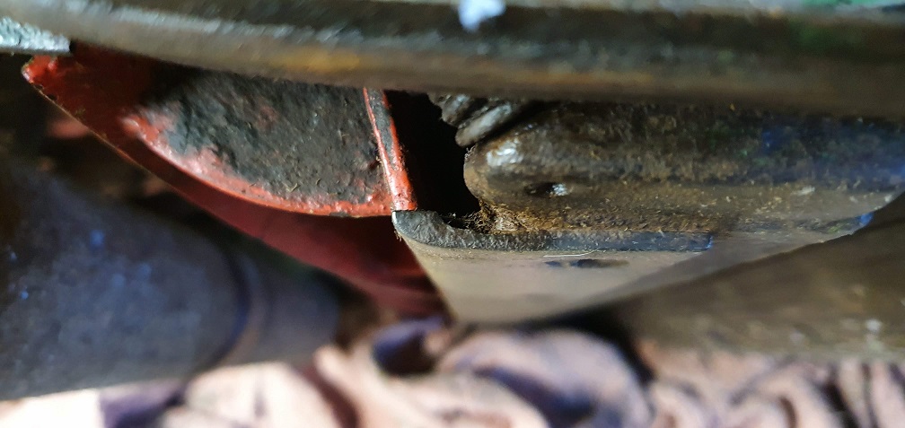
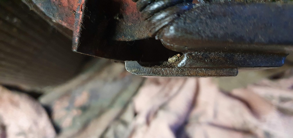
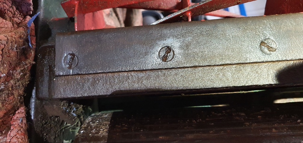
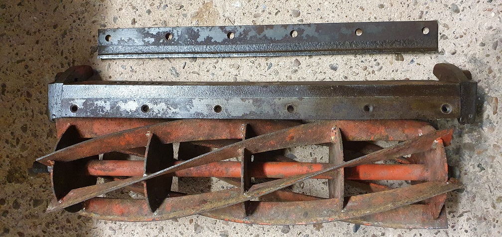
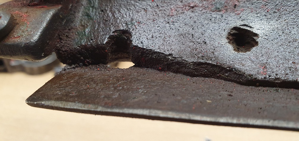
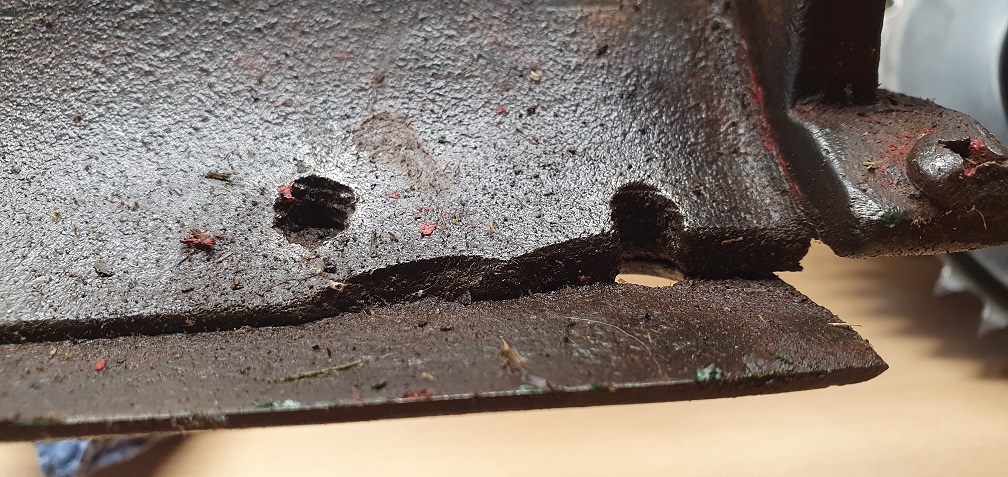
Looking at the now 'spare' sole plate I have which has the incorrect bottom blade attached, I may not need to get this one repaired, providing I can get the blade screws out of the remaining sole plate. Just to show why the outer most screw holes could no longer be used, both ends of the sole plate are missing some metal - cause unknown
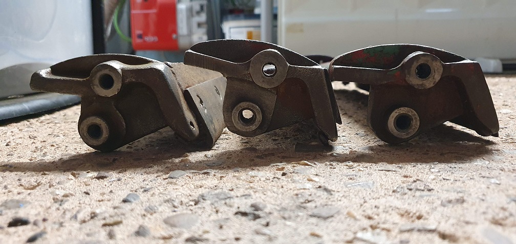
Onto the last cutting unit,
Onto the last cutting unit, which came as a spare originally. Bearing carriers were seized to the pivot points on the sole plate so needed a gentle talking to, in order to free them and remove them!
Dust covers were also on tight and had been punched in place
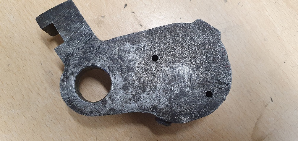
Interesting that these 2 carriers have the letter 'R' on them
There were 4 holes drilled by someone in the past, in order to tap out the bearing - probably either getting it wrong first time, or using the first 2 as markers to get the second set correct!
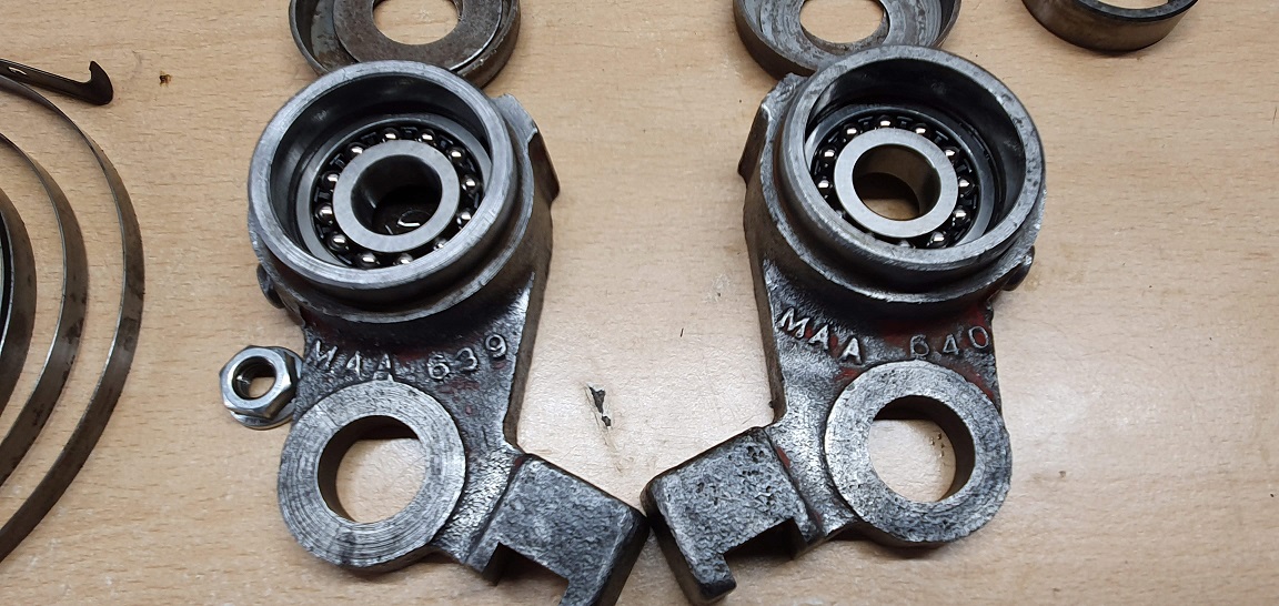
A clean up of the old paint reveals that these 2 carriers, as well as having a raised letter 'R' also have an additional 'A' appended to the part number of MAA 639A and MAA 640A
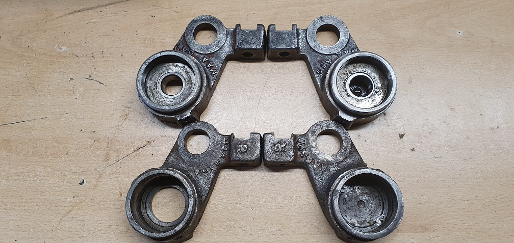
After some digging around online it appears these 2 carriers are actually for an Auto-Certes - as they are listed in the 'cross reference of piece part marks' as an 'Old Mark' number for the 'New Mark' numbers of LMSD 399 and LMSD 400 respectively
This may also explain why the sole plate they were attached to has a different shape to the two others I have, although I cann't find a part number anywhere on it. You can see the difference here - it has more of a right angle form rather than a shallow curve like the other 2
A few more pictures of
A few more pictures of progress - albeit a little slow due to a hip problem!
Showing the range of adjustment of the clutch in order to set the chain tension
Rebuilding the cylinder bearing carriers after pressing in the new RL5 bearings, cleaning out the oil lubricator and thread, and refitting, followed by the metal washer on top of the bearing, and then the felt washer soaked in fresh oil, and finally the dust cap refitted securely
Good bottom blade refitted to sole plate with new screws
so that's one cylinder and bottom blade unit ready for grinding.
Back to the clutches and the
Back to the clutches and the broken Oilite top hat bushes. Without knowing quite how much wear was on the inside of the clutch hub that the Oilite bushes press fit into, and one being a much looser fit in it's hub than the other, plus given the extortionate price of the new genuine bearing - and needing two!! - I ended up having two bushes custom made from SAE660 Hollow bronze bar, replicating the original bushes with the flange and oil hole, but without the brittleness of the original sintered bushes. This way they could be made to fit the exact sizes of my two hubs and also press fitted at the same time. Very happy with the results and they should last with the correct oil lubrication
New bush being pressed into place
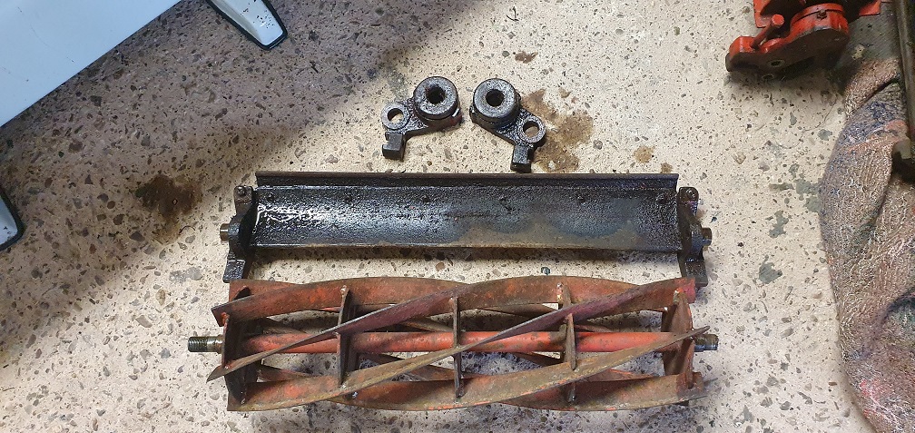
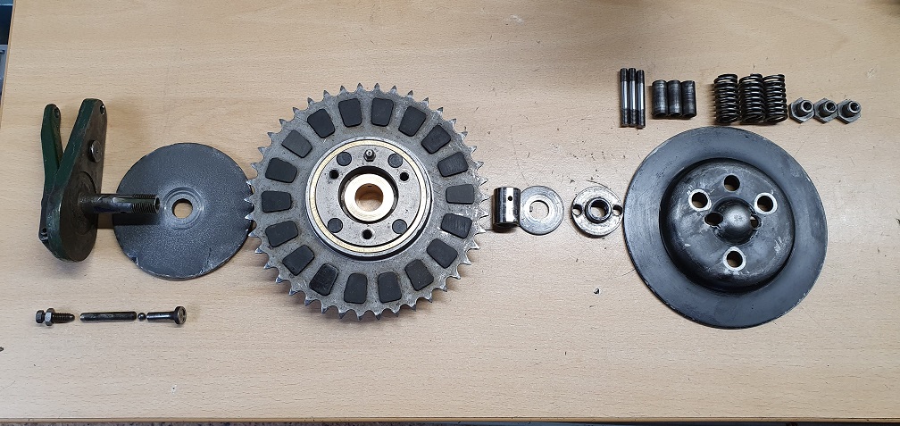
A picture to show the complete clutch assembly lineup
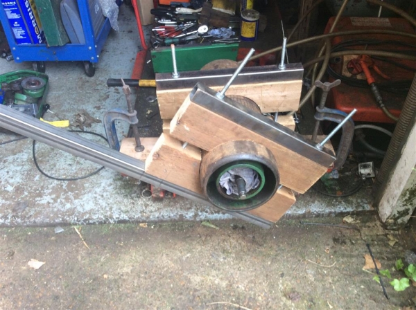
I also had a tool custom made
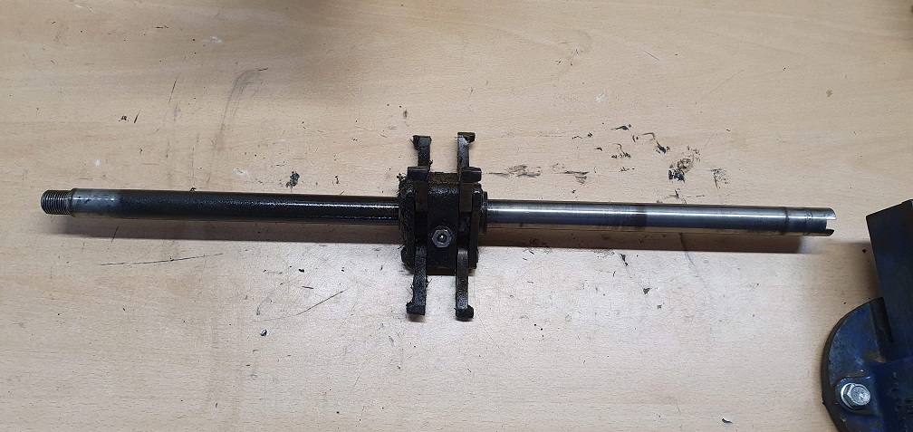
I also had a tool custom made in order to lock the non drive side end of the rear roller shaft, to allow the removal of the large roller sprocket (left hand thread) which took a fair amount of force! A mower clutch hub was the donor part, and this had some 3/4" silver steel pressed into the centre, and pinned in place, and then the 3/4" steel was cut to leave the male 'key' part which would hopefully achieve full engagement with the slot in the end of the roller shaft. The measurements were sent off and the tool produced very well and perfectly to spec, and it worked brilliantly
Making the tool
The tool allows the existing 3 bolts to be used, which hold the roller shaft plain bearing to the non drive side chassis. This provides maximum resistance on that side of the mower, allowing a good amount of force to be used on the sprocket to remove it
With the shaft locked firmly in place I could address the sprocket on the other side. I had read reports of the sprocket being tight, so I dug out a 6 foot length of pipe, carefully marked and drilled 2 holes in it - just the right distance apart for 2 long bolts to go down through and sit in opposing teeth on the sprocket. As I had 2 spare cutting cylinder height adjusting bolts, there were just the right size for the sprocket teeth, and I obtained the correct length with some spacers, allowing the nuts to be done up on the back face of the sprocket to firmly hold the bolts in place, and allowing the pipe to rotate free of the outer rim of the chassis
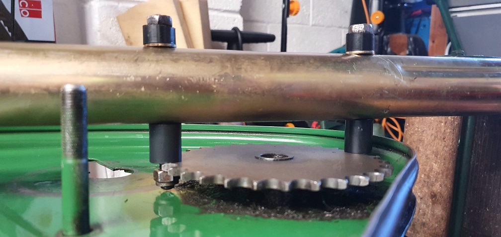
Give me a lever long enough...
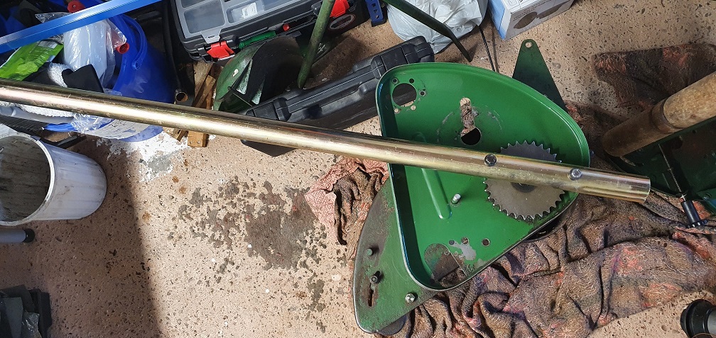
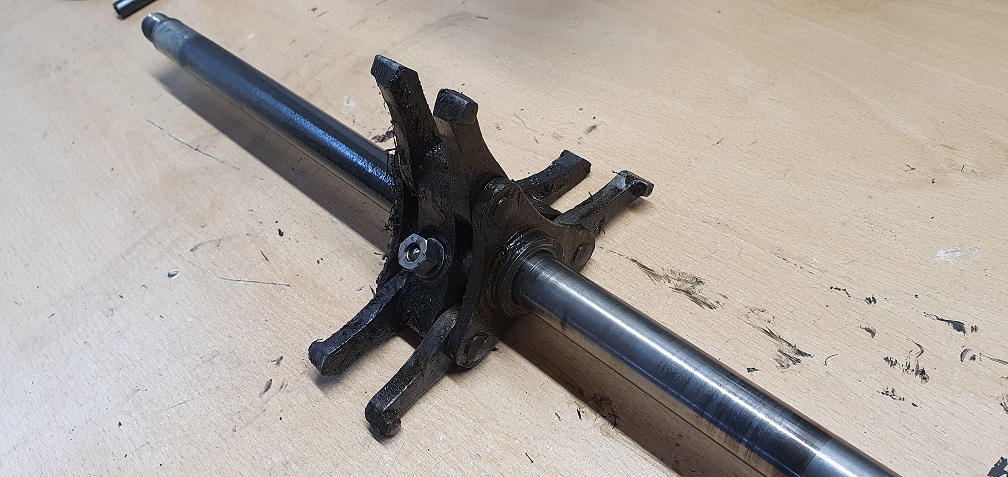
With the removal of these 3 bolts - holding the roller shafts drive side plain bearing, the rear roller could now be dropped out of the chassis
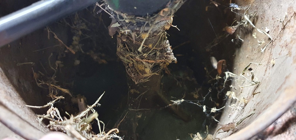
Time to re-home some spiders
Non drive side plain bearing that the rear roller shaft rotates in - the 20" version of the Marquis uses ball bearings in bearing carriers here, but just plain bearings on the 18" version
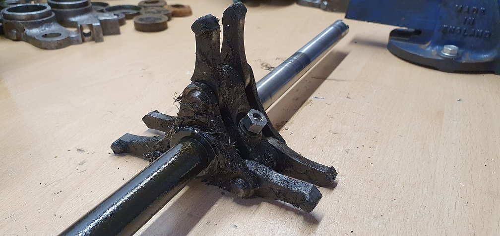
Then the distance piece can be removed after removal of the retaining grub screw
then the non drive side roller half can be removed from the shaft
revealing the 2 sets of pawls that engage with each half of the roller separately
Old grease and dirt were making some of the pawls stick in, and not able to fall freely down when the halves rotate on the shaft. The cleanup operation begins...
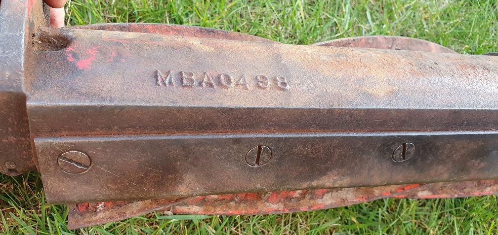
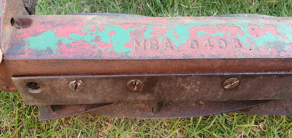
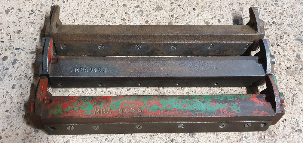
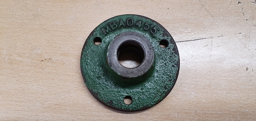
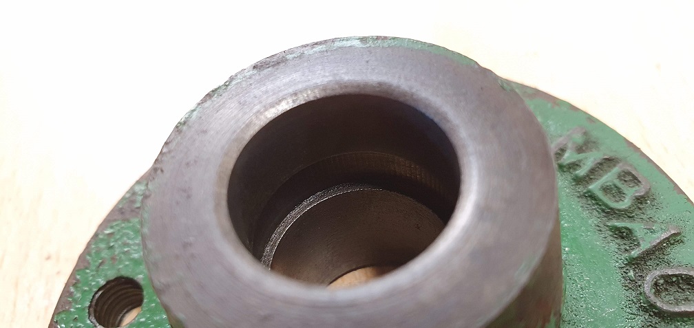
The non drive side plain
The non drive side plain bearing - MBA0455 - after a good clean up I can see an internal cutout which at a guess is to retain a certain amount of oil, once fed from the lubricator in the end of the shaft?
That's one half cleaned up, allowing the examination of the lubricator in the roller half, accessed through the hole in the roller
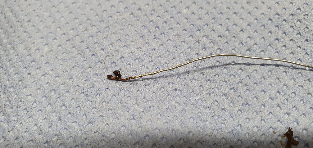
The same size head as the other lubricators around the mower, although these ones are press fit as opposed to threaded fit. Using some thin gauge wire, I thought I was feeling the resistance of the ball and spring inside the lubricator, however it turned out to be, you guessed it, compacted grease! I good clean through with the wire and some cleaning solution revealed no ball and spring inside - just an open ended lubricator - not sure if this is how the press fit lubricators are supposed to be? Seems strange given the location that dirt could work its way in, without the barrier of incorrect grease. I suppose its a relatively small hole so maybe a non issue.
Wire poking through removing old grease
Flushed clean and compressed air to follow
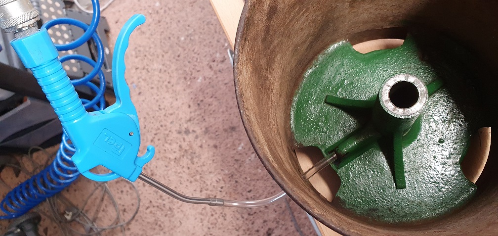
This lubricator feeds oil to the roller shaft
So that's one half cleaned up and sorted, now for the other half....then I get to do it all again on the second mower.....
Drive side sorted now also.
Drive side sorted now also. Rear roller shaft lubricator removed, lubricator tube removed - both full of old grease. Good intentions by previous owner!
Lubricator tube unscrews from the drive side bearing
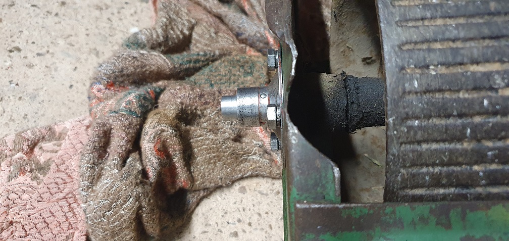
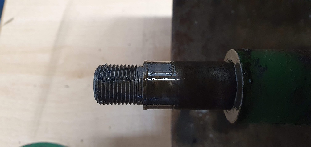
The drive side plain bearing wouldn't pull off the end of the shaft, as the base of the left hand thread had mushroomed out slightly, so after some advice from a fellow forum member I managed to flatten down the edge of the shaft enough to allow the bearing to pull off slowly
The distance piece simply slides off the drivers side of the shaft - oddly the parts diagram shows it is retained by a grub screw, the same as the non drive side distance piece, however no grub screw and no hole for one!
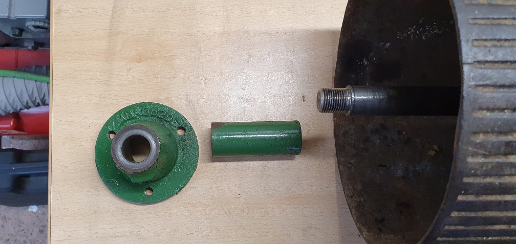
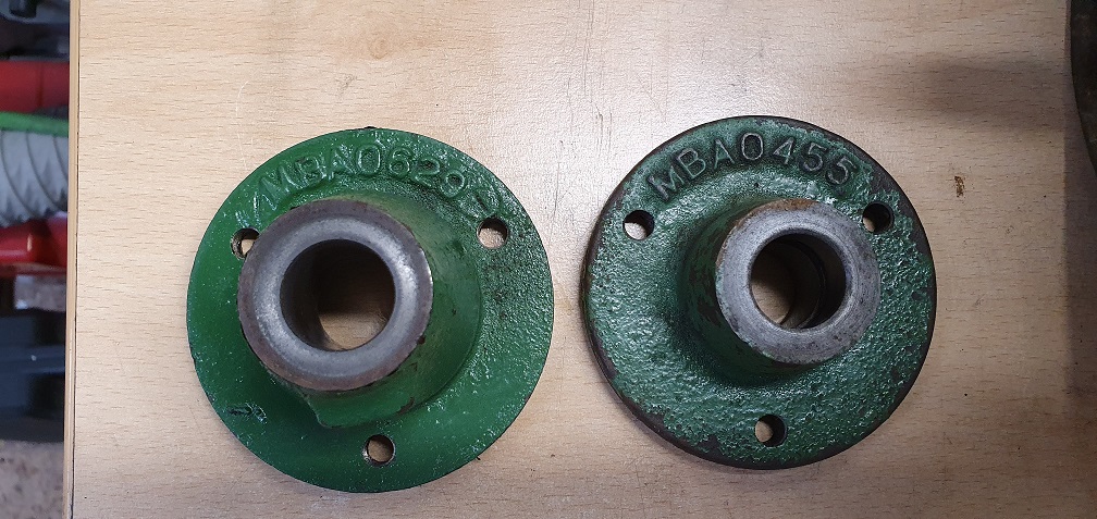
Both shaft bearings - Drive side MBA0629 Non-Drive side MBA0455
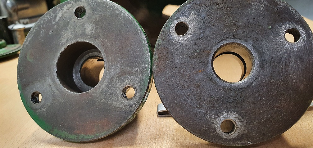
A large recess inside the drive side carrier (above left) - not sure of the purpose of this - almost like a bearing could go in there, like on the 20" Marquis - although the bearing housing on the 20" has part number MBA1422, so is different to this part.
This meant the shaft and ratchet/pawl mechanism could be removed to be cleaned up
A lot of thick tar like mess, making some of the pawls stick and not swing freely like they should, so a good degrease and hot wash to remove all the crud
The nut screws onto the thread on the end of the cotter pin - which holds the mechanism to the shaft
All clean and all 6 pawls singing about freely like they should, with no damage to any of them thankfully.
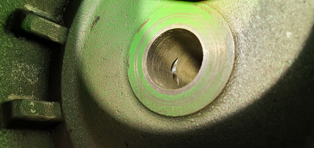
Back to the non drive side end of the roller shaft - where the slot is, which has a lubricator screwed into the end of it. Again, this passageway was full of old grease, so required flushing out
The hole in the shaft wall feeds oil to the inside of the plain bearing
The drive side roller half lubricator also received the same treatment as the other side
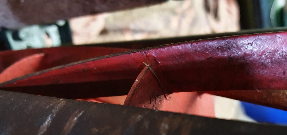
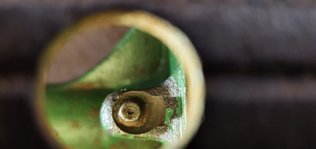
Theres a little bit of play
Theres a little bit of play between the roller spindle and the plain bearings - mainly the drive side bearing. Perhaps some degree of play is desirable to allow the oil that is pumped in to the lubricator tube to disperse around inside the bearing, but this explains why the chassis on the mk4 would move slightly in a horizontal / diagonal direction while the roller remained still. It's not going to affect the mower in terms of it mowing grass, and I imagine the only way to reduce this would be to insert some sort of sleeve into the plain bearing to take up the space between the bearing surface and the spindle. This would bring the bearing diameter back to probably what it was when new, but probably not necessary.
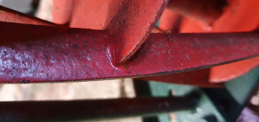
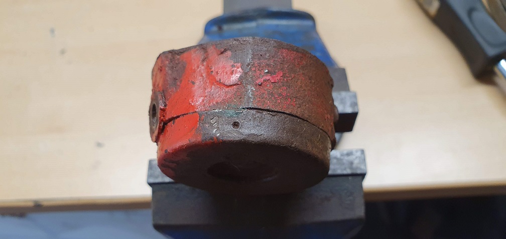
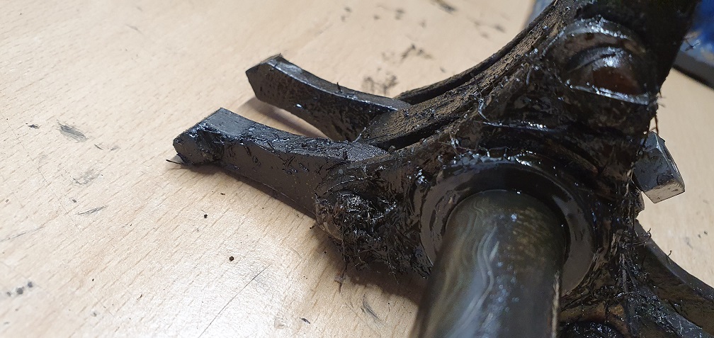
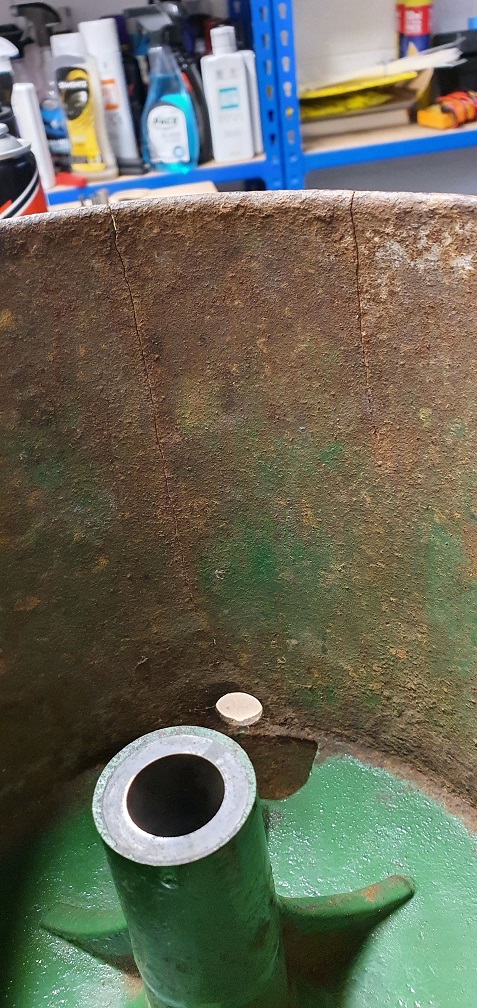
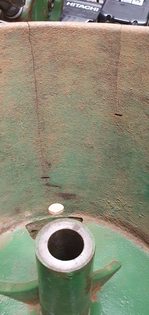
One other thing that has come to light now that the rear roller has been cleaned, is that there are 2 hairline cracks in the cast iron drive side roller half. I suppose with being cast iron and the age, it's probably taken a knock in the past or maybe even been dropped. Again not going to affect the use of the mower as structurally it's still in tact enough to perform it's duties. From what I've read about welding cast iron, it probably doesn't warrant the work/cost as it is perfectly usable as is. Would it be worth reinforcing some other way, to possibly help prevent it getting any worse - using JB weld plus some sort of reinforcement on the inside?
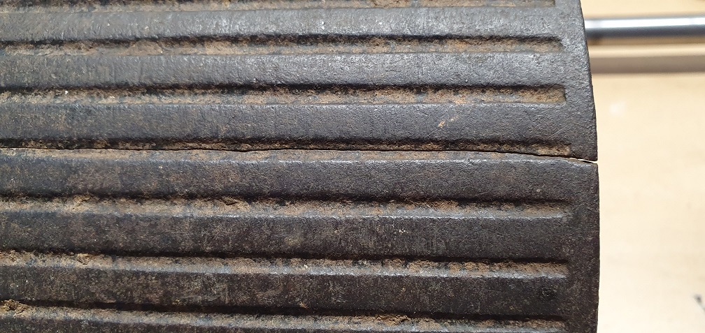
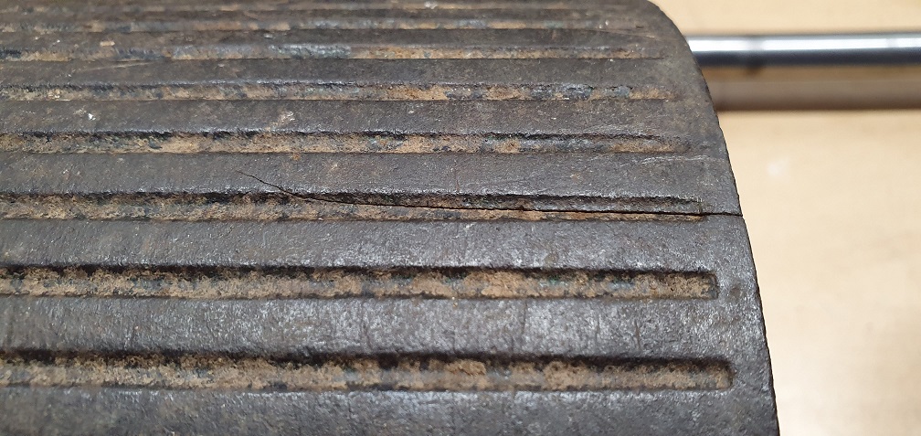
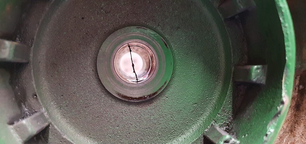
It looks as though one of
It looks as though one of those cracks extends all the way to the lubrication access hole - not good. Normal procedure is to drill a hole at the end of the crack to prevent it propagating . A skilled welder ( as opposed to someone who can weld) using the right rods or filler wire and the correct pre heat and controlled cooling should be able to repair those cracks. I’ve had a few done in the past with satisfactory results. As good as JB weld is for some jobs I would say that this would be a “a job too far”.
Thanks Angus, I've cleaned up
Thanks Angus, I've cleaned up the surface rust on the inside of the roller to get a better look at the cracks, and fortunately the longer one doesn't reach the lubrication access hole. The small crack is around 2" and the larger one just under 5" and I've marked the end of the cracks
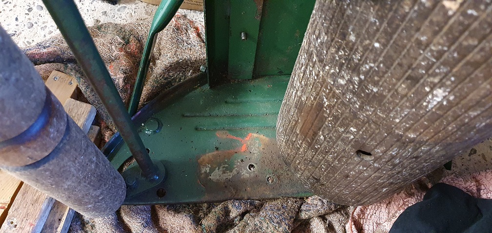
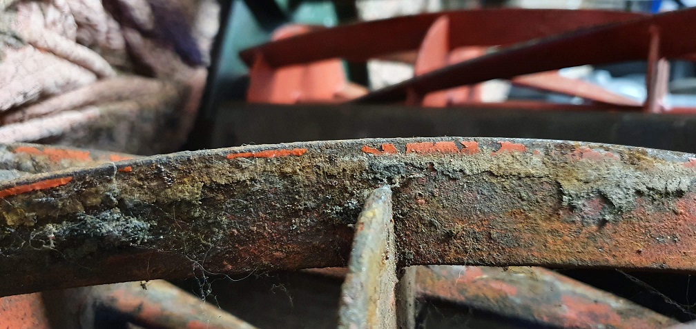
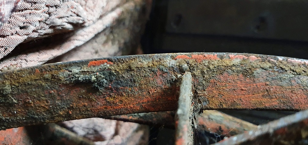
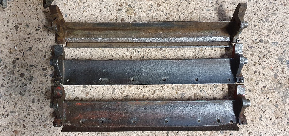
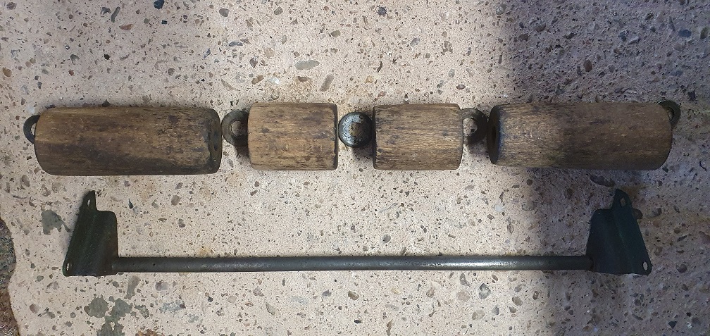
I will make some enquiries locally to see if I can find a good welder. There is a reputable blacksmiths / Ironworks nearby who mention cast iron welding on their information page so I'll see if they can help. I can get started on the rear roller of the MK4A in the meantime. A couple of remaining questions - the scraper bar on the rear of the chassis, for clearing mud/debris from the rear roller, should that be flat or curved? Both mowers have an irregular shape to this them, looking like they have been twisted to perhaps get closer to the rollers
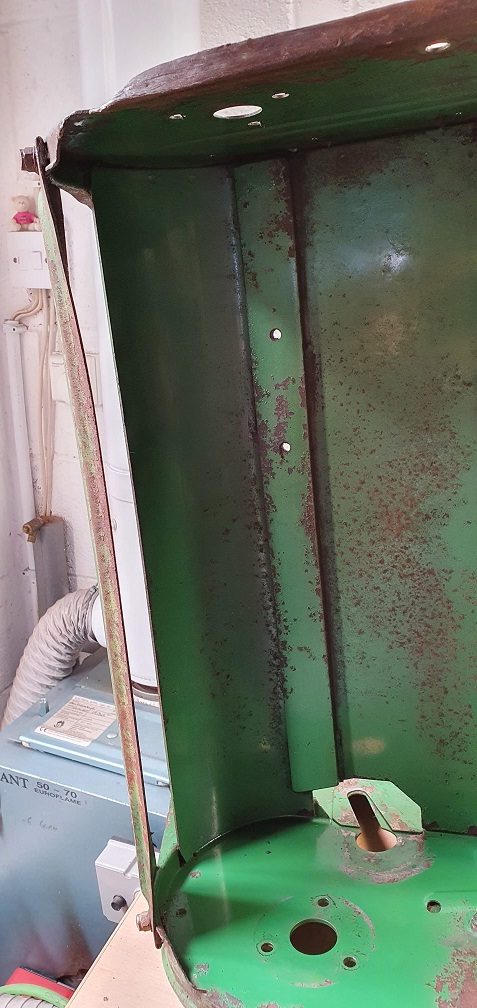
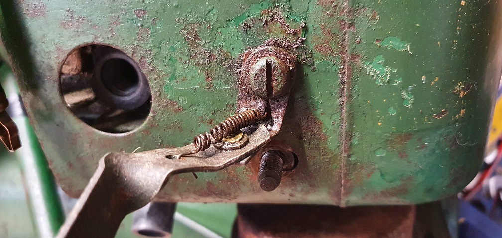
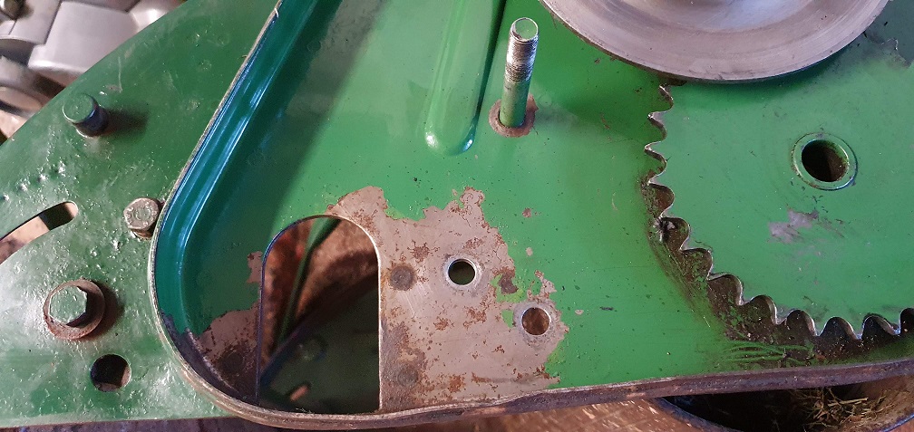
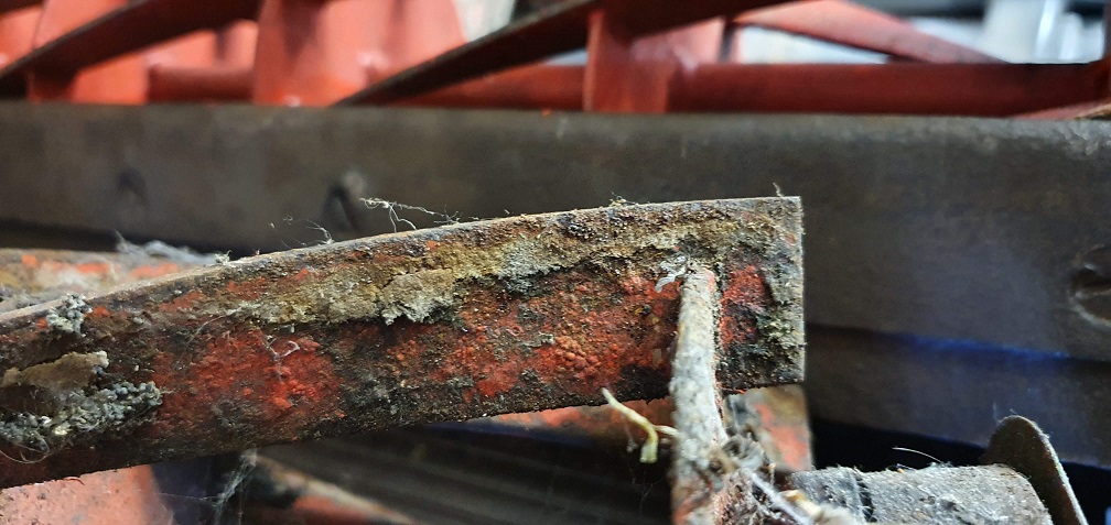
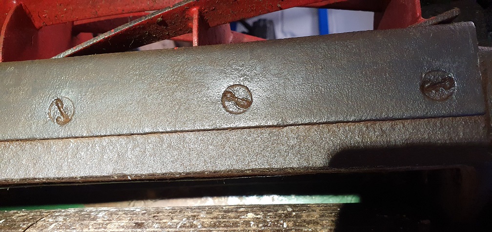
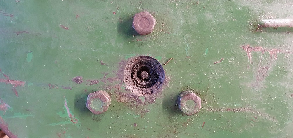
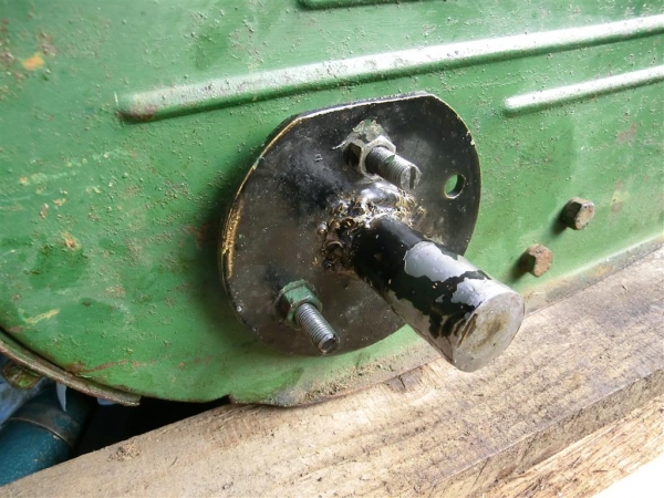
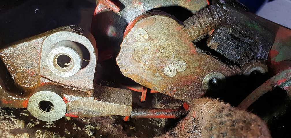
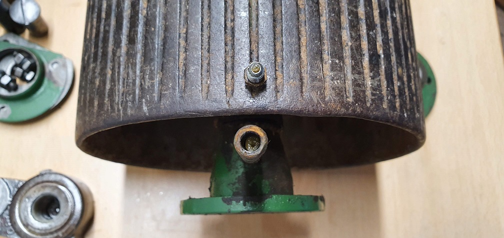
Secondly, and purely out of curiosity, can anyone tell me what the 'x' shaped raised pattern and 2 holes are for on the drive side chassis plate here:
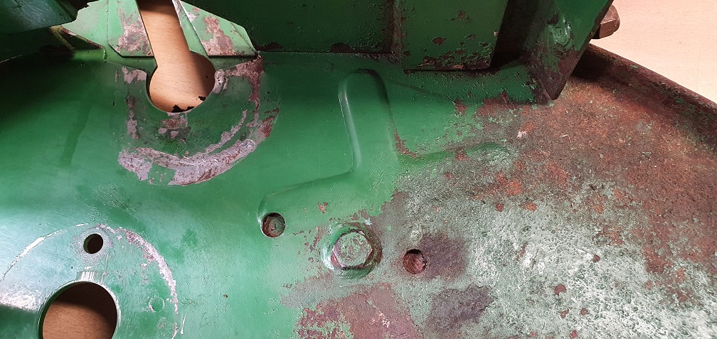
The welded bolt head is for the stud that the chain case cover hole fits over and is then held in place by the large flat head 'nut', but I can't think of the purpose of these other features - unless there is something fitted there on the 20" model or another earlier or later Marquis variant?
The welded bolt head is for
The welded bolt head is for the stud that the chain case cover hole fits over and is then held in place by the large flat head 'nut', but I can't think of the purpose of these other features - unless there is something fitted there on the 20" model or another earlier or later Marquis variant?
Don't quite follow the stud and nut. The one that I’ve just looked at has a hex head bolt inserted from the inside with its head tack welded to the frame.
Cross shaped swages are, I presume, to stiffen the side plate to support and keep in line the traction clutch etc. As for the vacant holes - no idea.
Scrapers. Yes, they are slightly curved longitudinally.
Thanks - 'Cross shaped swages
Thanks - 'Cross shaped swages' - a slightly better description than my own!
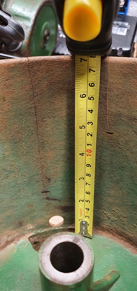
Front wooden rollers next - the 4 individual wooden pieces are generally in ok condition, with just mild tapering on the end of the two longer sections
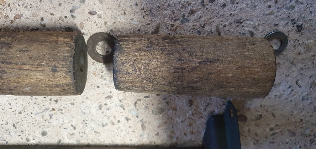
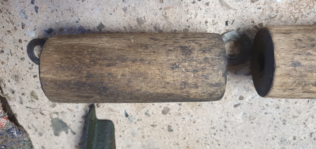
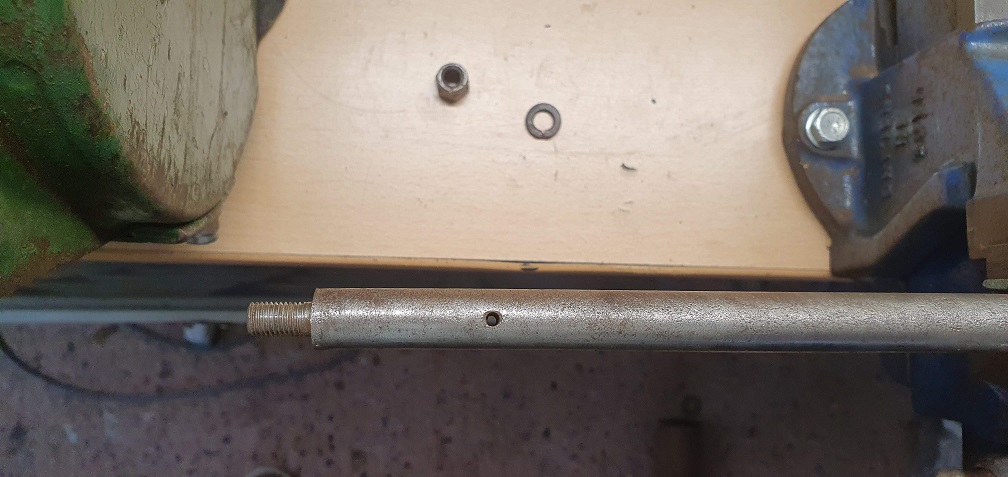
A cleanup of the spindle to remove the sticky residue and surface rust in patches, revealed a hole at either end, a couple inches from the ends
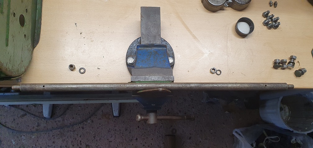
Curiosity strikes again :)
As I'm not painting any of the chassis, and possibly not the cutting cylinders (undecided) a new set of rollers would purely be for cosmetic effect, as these ones have life left in them, and new ones may look a bi tout of place against the rest of the mowers patina. Any suggestions for a light spruce up and preserve - perhaps a light sand and a coat or something like cuprinol to remove the grime, and maintain the used look but offer some protection in use?
There's still many tons of
You can add to that,Cycle Thread as I found to my surprise when restoring a JAP engined Gardenmaster cultivator. A useful supplier for such oddities is Namrick of Brighton. ( I’m sure that there are others)