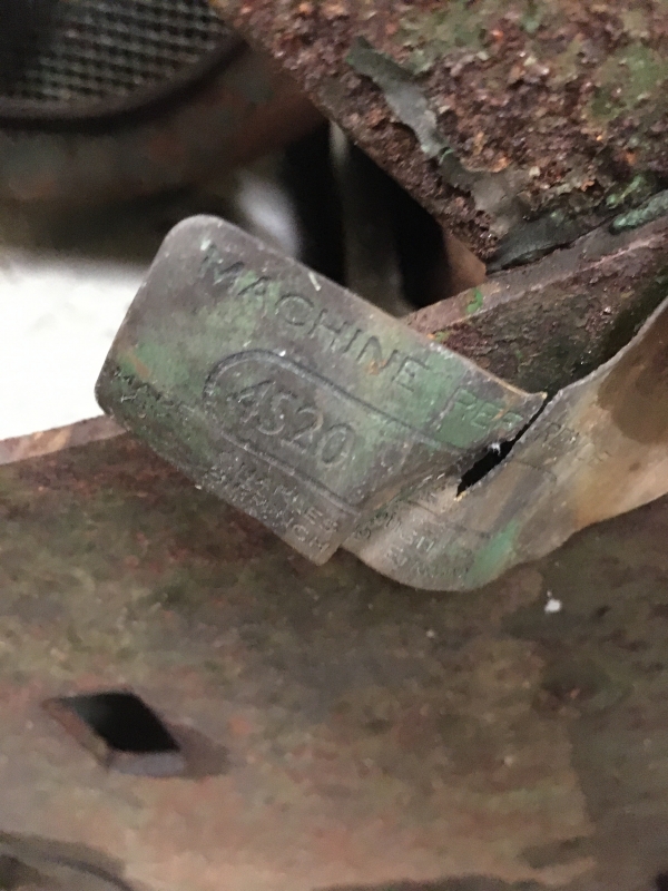
Atco 20" with tag 4520
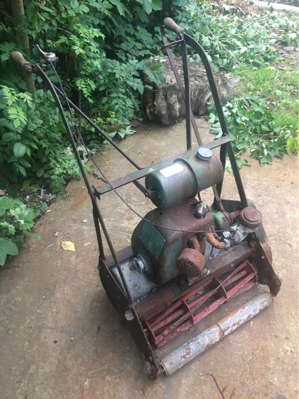
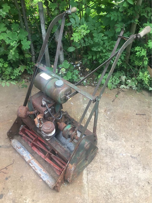
It seems mowers are like buses --they come in 3s. No sooner had I acquired an Atco F24 2068 which has been a subject of correspondence on this forum when I was offered a similar for spares. It however is in better condition than the one I was restoring--a nice dilemma to have.. I then found a real 'project' Atco mower with the tag 4520 which would imply 20" built in 1945. It certainly looks its age if it is genuine and will keep me busy during this second lockdown (Aberdeen). .
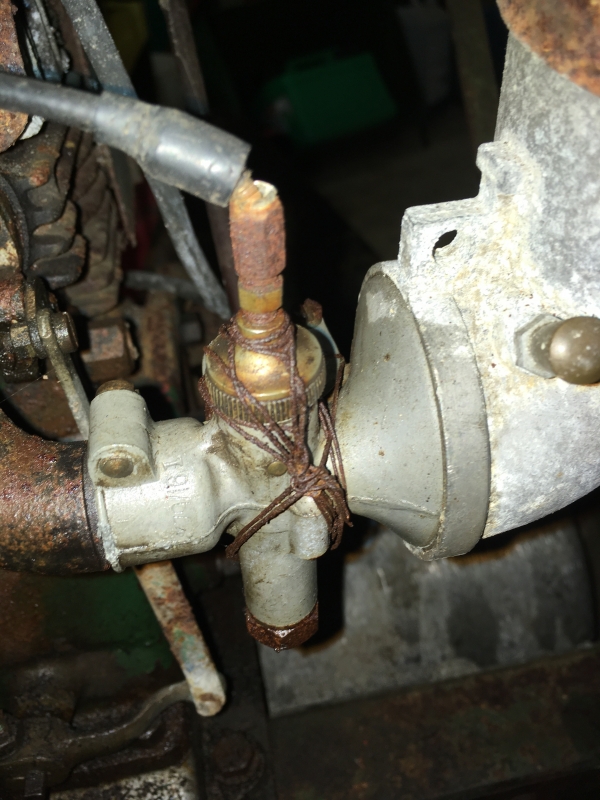
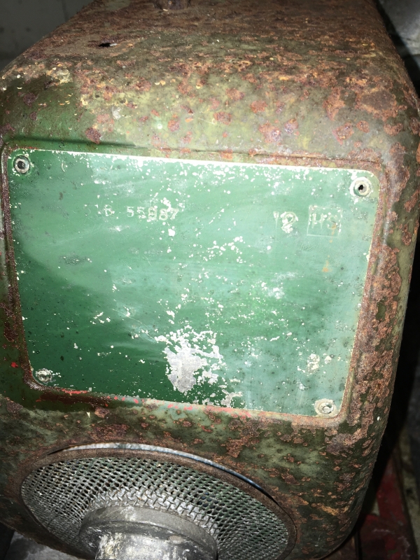
Herein lies the rub. I can find nothing online on this model. It is 20" cut with flat handles and a bar clutch. It has a 4stroke? villiers engine and as far as I can make out the number on the plate is 3518 559(8?)87. It has a pepperpot exhaust and an Amal 379 carb. It has an 18mm spark plug. No kick start only a pulley for a loose cord. See photos. Could it be a hybrid?
Any help would be much appreciated. Already I see parts of the carb. which will need to be sourced so any suggestions for this and other spares would be welcome.
Thanks
Forums


I’ve never seen that style of
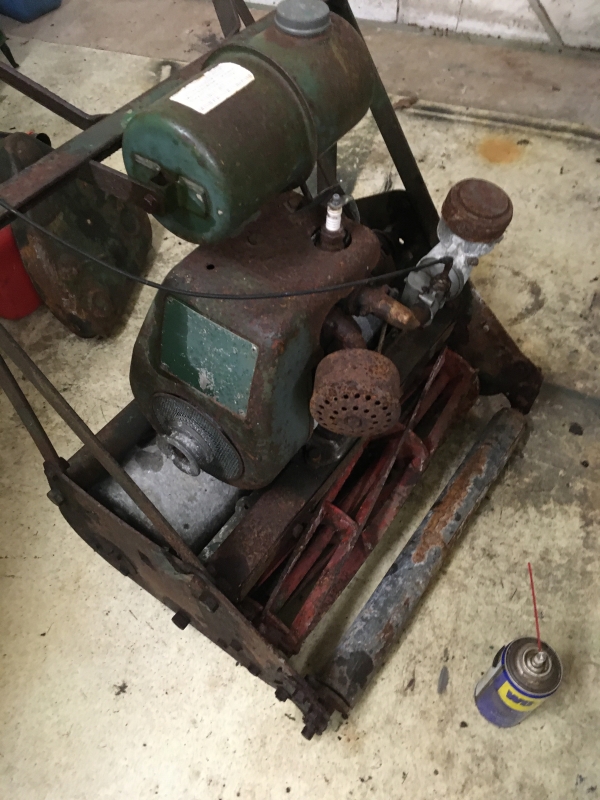
I’ve never seen that style of Atco / Villiers combination with that Amal carburettor - more often seen on the F12 Sloper engine.
I wonder whether the carb is a transplant?
Have another look, I reckon
Have another look, I reckon it is 4S20, the engine is a Villiers mk12. It is also another Atco fitted with the wrong carb, that is an Amal from a BSA/Villiers sloper engine.
EDIT: know I have had a chance to look, you need a Villiers S12 carb to get it back to original.
Stealing the questions from
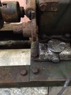
Stealing the questions from David the original poster of this thread but have a question pertaining to this mower. I note that the motor is mounted on an angle iron frame whereas almost all Atco lights I have seen of this era has the rods with pipe sleeves running across, is there any reason Atco used this angle iron frame?
Geoff.
That isn't really a
That isn't really a lightweight mower, it is the great grandad of the 20 inch HD and the engine was designed to be bolted to a flat surface, unlike the earlier two stroke engines.
Hi All,
Hi All,
From the documents that I have seen, the Atco 4S20 was released in 1957/8 (Series 202458) as a more professional 20" mower. There was also a 24" version known as the 4S24. The 4S20 cost £87 12s 3d new in 1958. They were fitted with a kick start Villiers Mk 12 with a Villiers S12 carburettor. They are a good little unit and do a good job.
The engine on this mower is original and appears to have had the kick starter removed. This mower is also a slightly later production as when originally released these mowers had the torpedo shaped fuel tank. These mowers were replaced by the HD series (as indicted by hortimech). In view of this, I suggest the mower would be circa 1959-1962.
Kind regards,
Sir Chook
Thanks to all for you
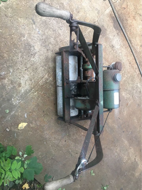
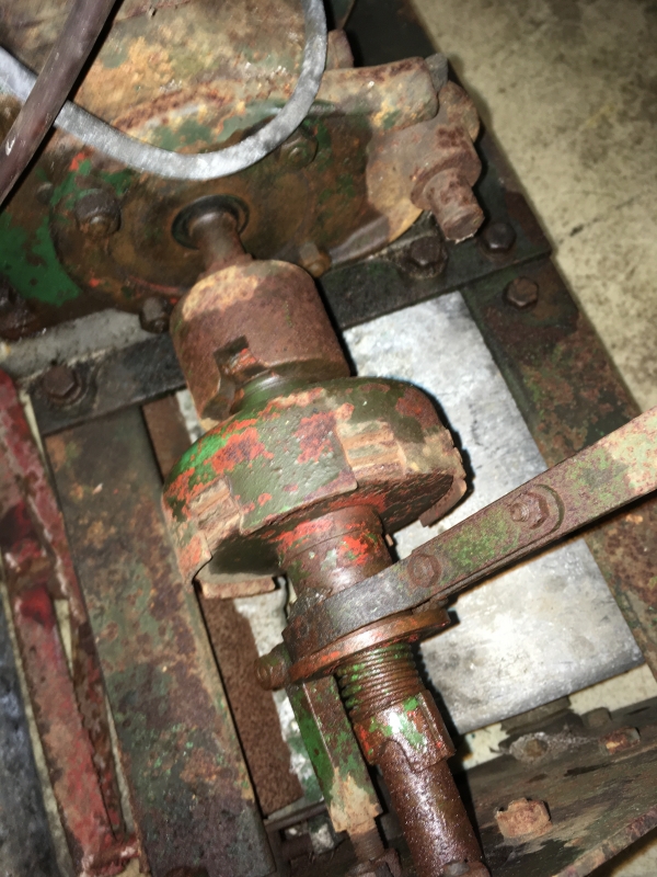
Thanks to all for you comments.All have been very helpful. I attach a couple of pics which pertain to some of the comments. It does look as if the central kickstart has been there at one time with a pivot plate being bolted to the engine. However that might imply that the engine (or other parts) are not odriginal. Certainly the engine is bolted to a plate which in turn is bolted to the frame indicative perhaps of a later modification and non standard engine.
If there was a kick start as original is there room for it with this layout. Certainly at the other side of the engine there is enough space for a recoil starter.
Can anyone provide details and parts if I was to restore the kickstart?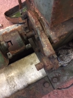
Here's the Atco model list
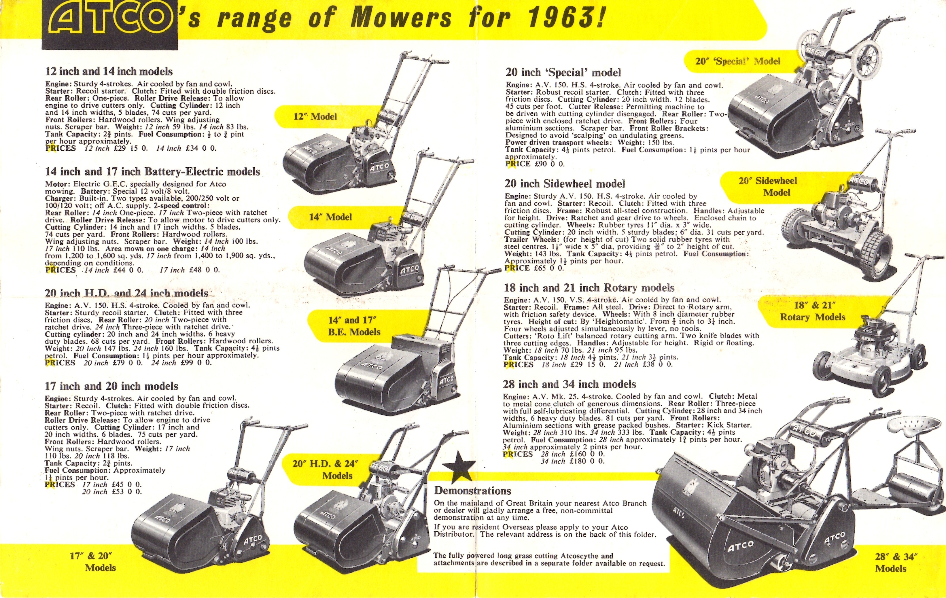
Here's the Atco model list for 1963. As you can see there are actually three different variants of a 20" model. Two of them are listed as having AV (ie Atco Villiers) four-stroke engines but the third only claims to have a "sturdy" 4S.
Do you know what is really
Do you know what is really sad, I have worked on all of those machines in my working life.
The sturdy 4-stroke is actually is actually a 75cc Suffolk, but I didn't think Atco used them until 1964 or 5 when Qualcast bought Atco.
Coming back to the OP's machine, it looks fairly original to me apart from the wrong carb and missing kickstart, the engine mount plate is original.
I think I am getting closer
I think I am getting closer to what my machine is and should be. As regards the kickstart can you tell me what is missing or direct me to an exploded diagram of what should be there. There are a couple of items on the e auction site (ref garlidd) with parts of a 20 kickstart some rather worn but I am not sure what all I need. Can anyone help identify the missing parts
Thanks
Where as the OP's machine
Where as the OP's machine appears to have a Villiers MK12 with a kick start the one on the above leaflet has a Villiers Lightweight with a recoil, so presumably a slightly later model.
Edit Whoops I now see that it says 1963!!
2nd edit
Some thing here that may be of interest
https://www.dropbox.com/s/26m4v2r8v21sb6n/Atco%20B13%20D7%20F12%20Parts…
Sorry Wristpin, wrong model,
Sorry Wristpin, wrong model, best I can find is this: https://www.outdoorking.com/forum/ubbthreads.php/topics/19483/Re:_Atco_…
Which was posted by someone called Sir Chook
Hi All,
Hi All,
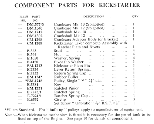
Unfortunately, I do not have a more detailed diagram for the kick start mechanism that hortimech has provided the link to. I have been able to find the parts list though and have attached it for information. This is from the Villiers Mk12 Operating Manual and Spare Parts List.
Kind regards,
Sir Chook
If you go right to the end of
If you go right to the end of the Dropbox file that I attached to the end of my post #12 it shows an engine mounted kick start in detail. - not the correct one?
EDIT
Here's the whole manual
https://www.dropbox.com/s/9x7r9ul8dnndmt1/Atco%20F10%20and%20H50001.pdf…
OOPs, yes it is, just didn't
OOPs, yes it is, just didn't expect another parts list after the first one.
Note to self: scroll to end of PDF's
Thanks to all yet again and
Thanks to all yet again and to wristpin for the end of pdf diagram of the kickstart mechanism. I now see clearly what is missing. The fun now starts to source parts still in a reasonable state.
I now have the engine off and am looking at removing the kickstart boss and the rope pulley at the other end. Are these conventional RH threads or is either a LH thread?
Attempting to remove the
Attempting to remove the magneto on my F12 motor and noted on the exploded diagram there isa circlip somewhere. I can see no sign of this. Is it small and within the nut or outside ? The nut slackened and then stuck. It rotates about 3 turns either way and jams. Help!!
The flywheel sits on a tight
The flywheel sits on a tight fitting taper on the end of the crankshaft. When the nut slackens and then goes tight it is ready to pull the flywheel off it’s taper. You need to devise a way of holding the flywheel ( not a bar through the fins) , Villiers show a form of strap wrench in their manuals. Then to undo the nut you need a well fitting ring spanner or socket with a tommy bar that can be given a sharp smack with a soft faced hammer. Villiers used to supply two different sized box spanners and a special ring spanner designed to be hit. Some of those special tools are still available from Villiers Services , LS Engineers and, of course that auction site.
When it comes to reassembling the magneto the flywheel nut is tightened in a similar manner.
I have the fin assembly off.
I have the fin assembly off. (it was held on to the magneto by 4 small nuts). Can I now attach a puller to the body of the magneto now that the central nut is slack?
No, the flywheel is, as
No, the flywheel is, as Wristpin said, self-extracting, you need to hold the flywheel securely (in a way that will not damage it), use a well fitting socket on a T-bar and welly it hard in an anti-clockwise direction. Do not in any circumstances try to pull the flywheel off, you WILL damage it.
As Wristpin and hortimech
As Wristpin and hortimech both say, the flywheel is self-extracting - you need to hold it securely (a bar through the fins is a really good way of de-finning the thing and buggering your cooling...) and keep going when it tightens again, at which point the flywheel will pretty much pop off.
Conversely when you refit it takes a lot more tightening than you think. I presume that there must be a point when you risk pulling the crank through the side of the casting, but if you don't get it tight enough it will slip and your timing will go west. The original tool for this supplied by Villiers was designed to be thumped with a hammer - here's one: https://villiersservices.co.uk/index.php?main_page=product_info&product… - which gives you an idea of the required degree of delicacy.
at which point the flywheel
at which point the flywheel will pretty much pop off.
I think that you should prefix that “with a bit of luck”. !! They can be a struggle - read my recent post .
True - maybe I've been lucky!
True - maybe I've been lucky!
VILLIERS flywheel nut tools
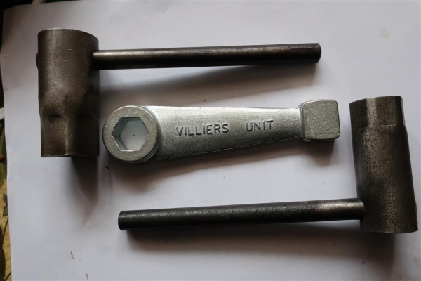 VILLIERS flywheel nut tools
Various homemade holding tools. Flywheel holder, bottom right.
Thank you, that answers the
Thank you, that answers the question I was pondering about a strap wrench!
You can make your own
You can make your own flywheel holder using an old seat belt, get a piece of square tube with the inside dimension to fit a half inch socket handle into, about 100mm long.
Cut a slot down the tube the length of which will match the width of the seat belt, you need to heat the ends of the belt so that it is larger than the belt as you are going to place this into the slot and it is to be held in there by the enlarged heated ends.
You should end up with the tube and a loop of seat belt with both ends in the slot, the loop needs to be large enough to go around the flywheel and enough extra to do at least two turns around itself to lock onto the flywheel using the socket handle.
If you Google strap oil filter remover, you should see exactly what I am trying to describe and they do work.
Geoff.
Thanks to all for your
Thanks to all for your helpful comments.
Thank goodness I did not try and pull it off. I must have got lucky as I now have the flywheel off !!!! But am now faced with removing the alloy back plate.which looked as if it was held on to the engine block by 4 nuts. All loose and shaft soaked in plusgas but still no movement. Do not want to use brute force in case I damage the back plate. Any more tricks I should learn?
Can I ask why you want to
Can I ask why you want to remove the backplate ? If it is to remove the piston, then you do not have to, just remove the sump and cylinder head, remove the bigend nuts and push the piston out (along with the con-rod).
Yes eventually I need to look
Yes eventually I need to look at the piston/rings but mainly to clean years of neglect. It will be easier to clean and paint if necessary the individual parts rather than try when together. (my philosophy anyway). Is there a problem removing the back plate?
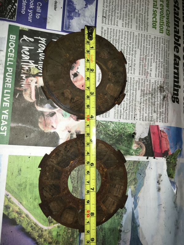
Subsidiary query. The clutch has cork inserts. Villiers are charging an arm and a leg to recork and I thought I would try myself. The steel plate is 3mm thick. How thick should the cork insert be. I gather cork sheet is unsuitable as it is reconstituted so they would have to be cut from champagne corks (what an excuse!!) Or I could purchase inserts and cut to suit. Thoughts please.
No, there is no problem in
No, there is no problem in removing the plate if you really want to ;-)
Try warming the backplate around the bearing with a hot air gun (keep away from the coil)
As for the clutch, anything is worth trying, but I would try and find corks from normal wine bottles rather than champagne bottles. As for the thickness, not sure, probably stuck out approx 1/8 inch either side (though it could be more), probably wisest to err on the side of too think and sand to the correct thickness.
What is the diameter of your
What is the diameter of your clutch plates. I may have one or two in various boxes of “ bits”.
Should you want champagne corks, I may have a few.
Don’t ask !
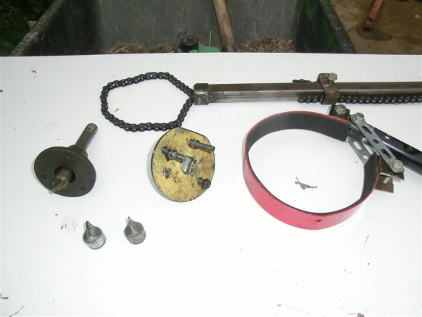
See attached photo. 14 cork
See attached photo. 14 cork inserts per plate approx 12.5mmx9mmx16mm and I am guessing at about 8mm thick (plate is 3mm)
Ah, that sort of clutch plate
Ah, that sort of clutch plate, I was thinking about the ones with round holes through them, or is that something else entirely ?
I somehow don't think measuring in millimetres is the way to go, your Atco was made in the days before metrication ;-)
Can I get some clarification
Can I get some clarification please. Previous comments have identified my machine as a 4 stroke 20" from around 1958. Sir chook suggested that engine is a Mk 12 and the carburettor should be a Villiers s12. Is a Mk 12 engine the same as an F12 engine? I am trying to locate an s12 carburettor but do not know what it looks like. I have found plenty info. on s10/2 carbs.
In the Atco parts list for 20" 4 stroke F12 the engine diag. is headed 'Group A 5032' and has a Carburettor diag. 'Group D 1015' . The engine diag. does not accurately illustrate my engine.
However in the exploded diagram supplied by wristpin at the end os his pdf showing the kickstart, the layout more accurately illustrates my model This page is 'Group A No 5028' Does this publication have a corresponding diagram of the carburettor which accompanies this engine?
Just seen a couple of s12 carbs on that well known auction site which do not look like Group D No 1015
Mms 7, 10, 12, cast iron
Mks 7, 10, 12, cast iron blocks, vertical cylinders. F15 likewise. F12, alloy block with an angled cylinder, hence the name Sloper.
Ignore the top of the PDF
Ignore the top of the PDF that Wristpin posted, go down towards the bottom of it and your machine is there and yes, your carb should be an S12, it is a slide carb like the incorrect Amal carb you have fitted.
If I understand it correctly, your machine was only produced between 1958-1962, so this would explain why I have only ever seen a handful
The mk 7, 10 and 12 were designed by Villiers and the F12 & F15 are BSA designed.
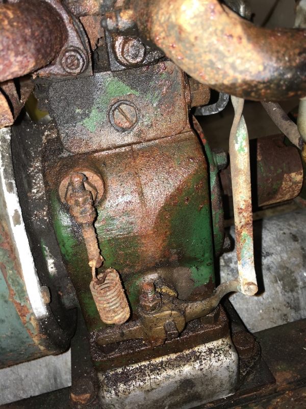
Another twist to the saga. I
Another twist to the saga. I have identified my engine number as 351B which according to Villiers and Paul Child of Meertens had a V-type No 59 carburettor fitted. However the manifold which is fitted to my engine is not correct for a V-type but appears from all the illustrations in the manuals I have found to suit an S12 as has been suggested. Also an s12 may be easier to find.
Not disbelieving what Meetens
Not disbelieving what Meetens have said, but I have only seen a few 20 inch Atco's fitted with a Villiers Mk12 and they were all fitted with the S12 carb. From my understanding, the 4S20 was released at the same time as the Atco 28 and 34 and they were supposed to be a 'family' aimed at commercial use (cricket clubs etc), so they were designed to look similar.
I think you will find that the external governor arm operates a butterfly in the inlet manifold, just like on the Atco 28/34, it had to be like that because the engine was fitted with a slide type carb (the S12)
Could it be that the main components of the engine (short block) were replaced at some time ?
S12 it is then. Happy to go
S12 it is then. Happy to go with your views.
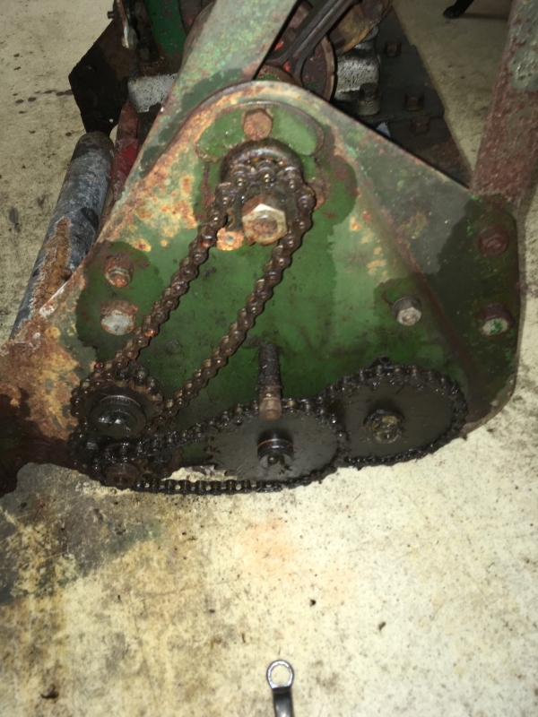
Next -- Bearings. I now have all the bearings off the machine and the parts list would indicate 4 designated Q11 and one Q 8. This would suggest that four of the bearings are the same and the fifth (on the clutch shaft) is different.
I have found
2 No LS7 V2 with 7 balls in the single race
1 No RL5 12 balls each in double race
3No NLJ5/8 12 balls each in double race
All are 5/8 ID x 1 9/16 OD and 7/16 wide
Can anyone clarify if indeed they all should be the same or are there different types for different locations ie front roller rear roller steel cage or aluminium cage
The only place you need a
The only place you need a self-aligning bearing is the clutch shaft bearing and even there you could probably get away with normal caged bearing. The cylinder and rear roller are fixed in place, so just need to rotate about an axis, that is they do not need to move on an arc. I personally would fit the best quality RL5-2RS bearings possible to the cylinder and rear roller (if they need replacing) and a self-aligning bearing to the clutch shaft.
Bearings get replaced when required and with a bearing that will fit, though most mechanics usually replace them in pairs
As far as the kick start
As far as the kick start mechanism goes I think you will struggle to find any parts in working order. The few mk 10 and mk 12 s I ve seen in last 20 years have all used a rope as the kick start has failed. Good luck with your search though .
The Mk 12 is a decent engine though, made to last with proper bearings and as stated, cast iron block.
Managed to find kickstart
Managed to find kickstart parts but it remains to be seem if they work. I will give it a try.
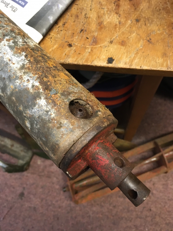
Moving to the front roller. Can anyone tell me if it is possible to dismantle this and if so how. I have tried twisting; pulling; soaking in plusgas but to no avail. I have yet to try heat. Thanks in anticipation.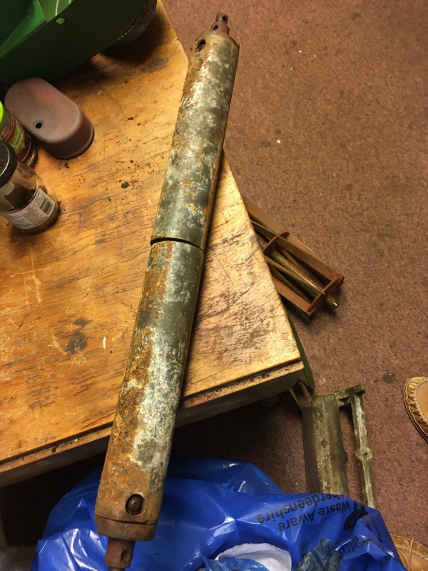
Forgot my second query. On
Forgot my second query. On the split rear roller there are meant to be 6 pawl springs. Onlt 2 have survived and only on one side .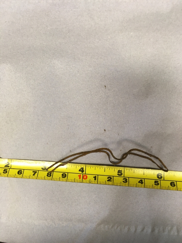
I have made one from spring wire and it seems to work. There are 3 per roller but only those on the driven roller side survived to indicate the direction they should be fitted. Do the other 3 face the same direction or are they handed?
You may or may not be happy
You may or may not be happy about this, but that isn't the original front roller, it is supposed to have wooden rollers.
The rear rollers freewheel forward and drive backwards, so you should be able to work out the spring direction, but I seem to remember they all went the same way.
I must admit I did wonder,
I must admit I did wonder, but as the rear rollers are also aluminium I thought it may have been an option.
It may be easier to find a set of 20" rollers than restore these.I can probably get wooden rollers turned locally but can anyone give the spec. for the axle Diam and length etc--or point me in the direction of a source?
Thanks
I believe the tag says 4S20
I believe the tag says 4S20 which would mean it's a 20" with a four-stroke engine (as opposed to the 2-S version possibly). It looks more like a late 50/early 1960s model to me.